Lift Shaft Pressurisation Systems
(Design, Supply, Installation, Testing, Commissioning & AMC for Fire Lift & Lift Well Pressurisation)
Design, Supply, Installation, Testing, Commissioning & AMC for Fire Lift & Lift Well Pressurisation
A lift shaft runs through every floor of a building. In a fire, that makes it one of the fastest routes for smoke to spread upwards, and one of the most valuable routes for firefighters if it stays clear. Compress India designs, supplies, installs, tests and maintains lift shaft pressurisation systems that keep fire lift and passenger lift shafts free of smoke and usable for firefighting.

Lift shafts are among the hardest spaces to pressurise. Landing doors leak heavily, moving cars create piston effect, and too much pressure can stop lift doors closing. We engineer around all three: leakage and piston-effect calculations, fan selection, injection points, motorised top vent dampers, multi-level pressure sensing, VFD control, and coordination with your lift manufacturer and fire alarm contractor.
- Lift shaft pressurisation system design, leakage calculation and fan sizing
- Fire lift shaft, passenger lift shaft and combined lift shaft and lobby pressurisation
- Lift shaft pressurisation with VFD-controlled fans and differential pressure sensors
- Lift fire-mode, fire alarm and BMS integration
- Testing with lifts in operation, Fire NOC witness testing support and AMC
Designing a high-rise core, answering fire authority comments or upgrading an existing tower? Send us your lift and core drawings for a design review and detailed quotation.
What Is a Lift Shaft Pressurisation System?
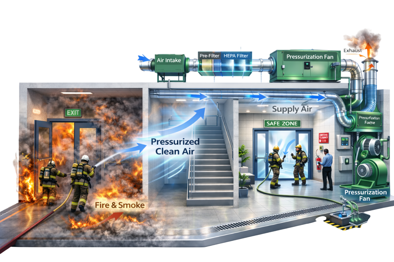
A lift shaft pressurisation system blows clean outdoor air into a lift shaft (hoistway) during a fire, raising its pressure above the fire floor. With the shaft at positive pressure, air leaks out through the landing doors instead of smoke leaking in, so smoke cannot use the shaft to travel to other floors.
Also called elevator shaft pressurization or lift well pressurisation, it is a dedicated shaft pressurization system made up of a pressurisation fan, a protected fresh air intake, supply ducts and injection points, a motorised vent damper at the top of the shaft, pressure relief or VFD control, and interfaces with the fire alarm and lift controller.
A pressurized lift shaft is most often required for fire lifts, which firefighters use to reach upper floors, but it is also used for passenger and service lift shafts in tall buildings to stop vertical smoke spread.
Why Lift Shafts Need Pressurisation During a Fire
An unprotected lift shaft can turn a single-floor fire into a whole-building smoke problem. Lift shaft smoke control prevents that.
Lift Shafts Act Like Chimneys (Stack Effect)
A tall, vertical shaft with openings on every floor behaves like a chimney. Warm smoke rises up the shaft and spreads out through landing doors on upper floors. This lift shaft stack effect grows with building height.
Preventing Smoke Spread to Upper Floors
Upper floors can fill with smoke even when the fire is many floors below, endangering people who were never near the fire. Positive pressure in the shaft blocks this route.
Keeping Fire Lifts Usable for Firefighters
Fire lifts let crews and equipment reach upper floors in minutes. A smoke-logged shaft or landing makes the lift unusable just when it is needed most. Fire lift shaft pressurization keeps it in service.
Protecting Lift Landings & Lobbies
Air leaving a pressurised shaft through landing doors helps keep the lift lobby clear, working together with lobby pressurisation to protect the whole lift core.
Fire NOC & Code Compliance
Indian building bye-laws call for about 50 Pa in core lift shafts of buildings 15 m and above, together with pressurised lift lobbies. A correctly designed, tested lift shaft pressurisation system supports Fire NOC approval.
How a Lift Shaft Pressurisation System Works
Lift shaft pressurisation must work in step with the lifts themselves. This is the typical sequence.
1. Fire Alarm Activates the Pressurisation Fan
A detector, call point, sprinkler flow switch or lift lobby smoke detector triggers the fire alarm, which starts the lift shaft pressurisation fan through a monitored interface.
2. Lifts Switch to Fire Mode
At the same time, the lift controller receives the fire signal. Lifts return to the designated recall floor, and fire lifts become available for firefighter operation.
3. Clean Outdoor Air Is Injected into the Lift Shaft
The fan draws air through a protected intake and delivers it into the shaft through one or more injection points along its height.
4. Shaft Is Kept at Higher Pressure Than the Fire Floor
The shaft rises above the fire floor's pressure, so air flows out through landing door gaps and smoke cannot get in.
5. Top Vent Damper Closes to Hold Pressure
The permanent vent at the top of the shaft would let the supplied air escape. A motorised damper in that vent closes when pressurisation starts, so the fan can build and hold pressure.
6. Pressure Control Protects Lift Door Operation
Too much pressure can stop lift doors closing properly. Pressure sensors and a VFD, or relief dampers, hold the shaft within a safe band so lifts keep operating for firefighters.
Main Components of a Lift Shaft Pressurisation System
Every component below is selected for the specific demands of a lift shaft – high leakage, moving cars and sensitive lift doors – and integrated by Compress India as one tested system.
Pressurisation Fans
Axial or centrifugal lift shaft pressurization fans are sized for the large airflow that landing door leakage demands, usually as a duty-standby pair on emergency power.
Fresh Air Intake with Smoke Detection
The lift shaft fresh air intake is placed away from smoke exhaust outlets, basement vents and kitchen exhausts, with a duct smoke detector that stops the fan or switches to a clean intake if smoke is detected.
Supply Duct & Shaft Injection Points
A lift shaft pressurization duct carries air to one or more openings into the shaft. Injection points are positioned to avoid blowing directly onto cars, ropes or landing doors.
Motorized Top-of-Shaft Vent Dampers
A motorised damper fitted in the shaft's top vent stays open in normal use and closes on fire alarm so the shaft can hold pressure. Its fail-safe position is agreed with the fire authority.
Pressure Relief Dampers
A lift shaft pressure relief damper vents excess air when landing doors close, protecting lift door operation in fixed-speed systems.
Pressure Sensors at Multiple Levels
Lift shaft differential pressure sensors at several heights – low, middle and high – capture the variation that stack and piston effects create along a tall shaft.
VFD Control Panel
The lift shaft pressurization VFD adjusts fan speed to hold pressure within its band as doors open, close and cars move.
Fire Alarm & Lift Controller Interface
Monitored modules link the system to the fire alarm and the lift controller, so pressurisation, recall and firefighter operation follow one agreed sequence.
Fire-Rated Cables & Emergency Power
Fire-survival cabling from an emergency-power-backed supply keeps fans and controls running during a fire.
Firefighter Override Panel
A panel in the fire control room shows shaft pressurisation status and lets fire officers start or stop it manually.
Types of Lift Shaft Pressurisation Systems
The right configuration depends on the lift's role, shaft height, number of cars per shaft and the lift machinery arrangement.
Fire Lift Shaft Pressurisation
A fire lift shaft pressurization system protects the shaft of the lift reserved for firefighters. It is the most common and most critical application, usually paired with a pressurised fire lift lobby.
Passenger & Service Lift Shaft Pressurisation
In tall buildings, passenger and service lift shafts in the core can also carry smoke between floors. Pressurising them limits vertical smoke spread and supports evacuation elevator pressurization strategies where lifts assist evacuation.
Combined Lift Shaft & Lobby Pressurisation
Lift shaft and lobby pressurization are designed together, so the shaft, lobby and floor form a controlled pressure cascade. This is the preferred arrangement for fire lifts.
Single-Point vs Multi-Point Injection
Single-point injection supplies air at one level, typically the top or bottom of the shaft, and suits lower shafts. Multi-point injection supplies air at several levels, keeping pressure more even in tall shafts and reducing the influence of piston effect.
Fixed-Speed Systems with Pressure Relief
The fan runs at constant speed and a relief damper vents excess air. This is simple and robust, but pressure varies more as doors open and cars move.
VFD-Controlled Variable Pressure Systems
A closed loop lift shaft pressurization system uses sensors at several levels and a VFD to hold pressure within a narrow band. Lift shaft pressurization with a VFD controlled fan gives the best protection for lift door operation.
Systems for MRL Lifts vs Lifts with Machine Rooms
In lifts with a machine room above the shaft, openings between shaft and machine room must be considered in leakage and relief design. Machine-room-less (MRL) lifts have their machinery inside the shaft, so injection points and vent dampers are positioned to suit the equipment and the lift maker's requirements.
Lift Shaft Pressurisation vs Lobby Pressurisation
Lobby pressurisation keeps smoke out of the space in front of the lift; lift shaft pressurisation keeps smoke out of the shaft itself. For fire lifts, the two are normally combined.
| Factor | Lift shaft pressurisation | Lift lobby pressurisation |
|---|---|---|
| Space protected | The lift shaft (hoistway) | The lobby in front of the landing doors |
| Typical pressure (Indian bye-laws) | About 50 Pa | 25–30 Pa |
| Main leakage path | Landing doors on every floor | Lobby doors and lift landing doors |
| Special challenges | Piston effect, lift door operation, top vent | Balancing with stair and floor pressures |
| Air distribution | Injection points into the shaft | Shaft with grilles or dampers on each floor |
| Main benefit | Stops vertical smoke spread and keeps the fire lift usable | Keeps the landing and approach clear |
Lift shaft pressurization vs lift lobby pressurization is rarely an either-or decision. We design both together so the lift core works as a single protected zone.
Lift Shaft Pressurisation vs Lift Shaft Smoke Venting
Indian bye-laws require a permanent vent of at least 0.2 m² at the top of lift shafts. Venting lets smoke that enters the shaft escape at the top; pressurisation stops it entering at all.
| Factor | Lift shaft pressurisation | Lift shaft smoke venting (top vent) |
|---|---|---|
| Principle | Positive pressure keeps smoke out of the shaft | Opening at the top lets smoke escape |
| Smoke in the shaft | Prevented | Allowed, then vented |
| Effect on upper floors | Protects every floor | Smoke may still reach upper landings on its way up |
| Fire lift usability | Shaft and landings kept clear | Shaft may be smoke-logged |
| Equipment | Fan, ducts, dampers, sensors, controls | Vent opening, often with louvre |
| Typical use | Fire lifts and core lifts in high-rise buildings | All lift shafts, as a basic requirement |
Elevator shaft pressurization vs smoke exhaust or venting is therefore not a like-for-like choice. In pressurised shafts, the top vent is fitted with a motorised damper that closes during pressurisation, so both requirements are met.
Pressure Hierarchy – Staircase, Lobby, Lift Shaft & Fire Floor
In a fully protected core, every space has its place in the pressure order, and air always moves from the protected spaces towards the fire floor.
| Space | Typical design pressure (relative to the fire floor) | Role |
|---|---|---|
| Escape staircase | About 50 Pa | Protected escape and firefighting route |
| Lift shaft (fire lift) | About 50 Pa | Stops vertical smoke spread; keeps the fire lift usable |
| Lift / fire lobby | 25–30 Pa | Buffer between floor, lift landing and stair |
| Fire floor | Reference (0 Pa), lower still with floor exhaust | Where smoke is generated |
These are values commonly specified in Indian building bye-laws; your approving authority confirms the final figures. Because the shaft sits above the lobby, air flows from shaft to lobby to floor through the landing doors, which helps keep the lobby clear too. The challenge is keeping the shaft high enough to block smoke but low enough for lift doors to work – which is why shaft pressure control matters so much.
Special Challenges in Lift Shaft Pressurisation
Lift shafts are harder to pressurise than staircases. These are the challenges that separate a working design from one that fails at commissioning.
High Leakage Through Lift Landing Doors
Lift landing doors have running clearances on every side, so they leak far more than stair doors. Elevator door leakage is often taken at around 0.06 m² per landing door, and a tall shaft has dozens of them, which drives very large fan airflows.
Piston Effect from Moving Lift Cars
A moving car pushes air ahead of it and draws air in behind it. Research by NIST found this elevator piston effect becomes much more significant at higher car speeds, particularly in single-car shafts where little space surrounds the car, and that injecting air at both top and bottom reduced the airflow needed to keep smoke out.
Lift Door Operation Under Pressure
Lift doors are moved by small motors with limited force. Excessive shaft pressure can stop doors closing, which takes the lift out of service. US building code practice for elevator hoistway pressurisation, for example, caps shaft pressure at 67 Pa for this reason.
Pressure Variation in Tall Shafts
Stack effect, wind and open doors at the recall floor make pressure vary along a tall shaft. Approaches developed for tall buildings include the basic elevator pressurization system, the elevator pressurization exterior vent system (venting the fire floor to outside), the elevator pressurization floor exhaust system (exhausting the fire floor), the ground floor elevator lobby system (an enclosed lobby at the recall floor) and VFD feedback control.
Basement-Connected Lift Shafts
Indian bye-laws say lifts should not normally serve basements; where they do, the basement lift lobby must be pressurised. Basement-connected shafts need careful intake and pressure design to keep car park smoke out.
Coordination with Lift Manufacturers
Door operator limits, landing door construction, machine-room openings and fire-mode logic all come from the lift manufacturer. Early coordination avoids surprises at commissioning.
Fire Safety Codes & Standards
We design lift shaft pressurisation to Indian requirements first, applying European or American lift and smoke-control standards where your project or lift supplier specifies them.
NBC 2016 Part 4 – Fire Lifts & Lift Shaft Requirements
NBC 2016 Part 4 sets the fire and life safety framework, and Indian model building bye-laws aligned with it set out specific lift rules. Lift enclosure walls must have a two-hour fire rating, and shafts need a vent of at least 0.2 m² at the top. Where lift shafts and lobbies are in the core of buildings 15 m and above, about 50 Pa is maintained in the shaft and 25–30 Pa in the lobby. Fire lifts must reach the top floor from ground level within one minute, run on a separate electrical supply, and have a grounding switch at ground level for the fire service.
Maharashtra Fire Prevention & Life Safety Measures Act
The Maharashtra Fire Prevention and Life Safety Measures Act, 2006 requires owners and occupiers to keep fire and life safety installations in efficient working order at all times, and to submit a Licensed Agency's maintenance certificate to the fire authority each January and July.
Local Fire Authority & Fire NOC Requirements
The approving fire authority reviews lift shaft and lobby pressurisation at the provisional Fire NOC stage and witnesses performance before the final Fire NOC is issued. We align the design and test plan with your specific authority.
EN 81-72 Firefighters Lifts
EN 81-72:2020 sets the European rules for firefighters lifts, which must operate under the direct control of the fire service, with additional protection, controls and signals. It includes protection of electrical equipment against water from firefighting. It is often specified by international lift manufacturers and premium projects.
EN 12101-6 / EN 12101-13 Pressure Differential Systems
EN 12101-13:2022 covers the design, calculation, installation and testing of pressure differential systems, including those protecting firefighting lifts, while EN 12101-6 covers the components.
NFPA 92 & ASME A17.1
NFPA 92 recognises elevator pressurisation as a smoke control method, and ASME A17.1, whose 2025 edition was published in 2026, governs elevator safety, including firefighters' emergency operation. US building codes add an elevator hoistway pressurisation option with a minimum of 25 Pa and a maximum of 67 Pa, a separate fan for each hoistway, and supply capacity of at least 1,000 cfm per landing door.
Lift Shaft Pressurisation Design Criteria
A lift shaft design must hold enough pressure to stop smoke without crossing the limit where lift doors stop working. These criteria define that window.
Pressure Differential Between Shaft & Fire Floor
The lift shaft differential pressure must stay positive on every landing, including the fire floor, with lifts at the recall floor. Indian bye-laws commonly specify about 50 Pa for core lift shafts.
Maximum Pressure for Safe Lift Door Operation
The upper limit comes from lift door operation rather than from people pushing doors. US code practice caps hoistway pressurisation at 67 Pa; we confirm the actual limit with your lift manufacturer for the specific door operators.
Leakage Area Through Landing Doors
Lift shaft leakage calculation totals landing door gaps, machine-room openings, shaft wall cracks and the closed top vent damper. Leakage flow is estimated as Q = 0.83 × A × √ΔP (Q in m³/s, A in m², ΔP in Pa).
Number of Open Doors During Firefighting
When lifts are recalled, landing doors at the recall floor may stand open, and during firefighting the fire lift's doors open on the fire floor. The design states which doors are assumed open and keeps the elevator shaft pressure difference positive on the remaining floors.
Stack Effect & Piston Effect Allowance
Temperature-driven pressure varies along the shaft, and moving cars cause short pressure swings. Margins are added for both, and very tall or high-speed shafts are checked with lift shaft pressure network modeling, for example using CONTAM.
Lift Shaft Pressurisation Design & Sizing
Our lift shaft pressurization system design turns those criteria into fan duties, injection points and control settings, documented for your Fire NOC submission and your lift supplier's review.
Fan Capacity Calculation
Lift shaft pressurization fan sizing starts from landing door leakage. For example, a 30-landing shaft with 0.06 m² per door, held at 50 Pa, leaks about 10.6 m³/s (roughly 38,000 m³/h or 22,400 CFM) before any open-door allowance. This is why lift shaft pressurization CFM is usually far higher than for a staircase, and why the lift shaft pressurization calculation must use realistic door data.
Injection Point Locations
Injection points are positioned to spread air evenly and counter piston effect, often near the top and bottom of the shaft for taller lifts, and placed clear of cars, counterweights, ropes and landing doors.
Dedicated Duct vs Builder's Shaft
A sheet-metal duct leaks far less than a builder's shaft and gives more predictable lift shaft pressurization static pressure. Where a builder's shaft is used, it must be rendered and sealed.
Pressure Relief Damper Sizing
In fixed-speed systems, the relief damper is sized to release the difference between fan output and leakage with doors closed, keeping pressure below the lift door limit.
Pressure Sensor Placement
Sensors are placed at several levels so the controller responds to the true pressure profile, and are kept away from injection points and door gaps that would give misleading readings.
Air Intake Location & Smoke Contamination Prevention
Intakes are located away from smoke exhausts, basement vents and openings on likely fire floors, with smoke detection and, where needed, a second intake with automatic changeover.
Standby Fan & Redundancy
Duty standby lift shaft pressurization fans with automatic changeover keep the fire lift protected if one fan or motor fails.
Power Supply & Cable Survivability
Fans, VFDs and vent damper actuators are fed from emergency power through fire-survival cables on protected routes. Lift shaft pressurization emergency power is planned alongside the fire lift's own separate supply.
Controls & Fire Alarm Interlocks
Lift shaft pressurisation is the one smoke control system that must coordinate with moving machinery. Our control sequences are agreed with the fire alarm and lift contractors before anything is wired.
Automatic Start on Fire Alarm
The lift shaft pressurization fire alarm interlock starts the fans on a confirmed building alarm or a lift lobby smoke detector signal, through monitored interface modules.
Lift Fire Mode & Firefighter Operation
The same alarm sends lifts to the recall floor and enables firefighter operation of the fire lift. Pressurisation is timed and set so recall and door operation are not disrupted.
Top Vent Damper Control
The motorised top vent damper closes when pressurisation starts and reopens on reset. Position switches confirm its status at the control panel and fire control room.
Pressure Sensor & VFD Control
Lift shaft pressurization with differential pressure sensors and VFD control holds shaft pressure within a band: high enough to stop smoke, low enough for lift doors to operate, even as cars move and doors open.
Intake Smoke Detection & Shutdown
If smoke reaches the intake, the system switches to a clean intake or stops the fan, as agreed with the fire authority.
Fan Status Monitoring & Alarms
Airflow or current sensing proves each fan is running; failures trigger standby changeover and alarms at the fire panel and fire control room.
Integration with Staircase, Lobby & Smoke Exhaust Systems
Lift shaft, lobby and staircase pressurisation and fire floor exhaust start in the agreed order, while AHUs serving the fire zone shut down. Lift shaft pressurization BMS integration logs every event for audits.
Benefits of Lift Shaft Pressurisation Systems
An elevator shaft pressurization system for smoke control protects far more than the lift itself.
Stops Smoke Spreading Through Lift Shafts
Positive pressure closes off one of the main vertical smoke routes in any tall building.
Keeps Fire Lifts Usable
Clear shafts and landings let firefighters use the fire lift to move crews and equipment quickly to upper floors.
Protects Upper Floors from Smoke
Occupants many floors above the fire are shielded from smoke that would otherwise rise through the shaft.
Supports Safer Firefighting
With the shaft, lobby and stair protected, fire crews can stage close to the fire floor and attack it with less exposure to smoke.
Compliance with Fire NOC Requirements
A calculated, tested and documented system supports Fire NOC approval, occupancy certification and Maharashtra's twice-yearly maintenance certification.
Limitations & Design Challenges
Addressing these challenges at design stage is what gets a lift shaft system through its witness test first time.
High Airflow Due to Door Leakage
Landing doors make lift shafts very leaky, so fans, ducts and power supplies are large. Accurate door leakage data and sealed shafts keep sizes reasonable.
Risk of Lift Door Malfunction at High Pressure
If shaft pressure exceeds what the door operators can overcome, doors may fail to close and the lift stops. Pressure caps and VFD control, confirmed with the lift maker, prevent this.
Pressure Fluctuations from Lift Movement
Moving cars create piston effect pressure swings. Multi-point injection, fast-responding VFD control and multi-level sensing keep pressure within its band.
Whistling & Noise at Landing Doors
Air escaping through narrow door gaps at high pressure can whistle. Holding pressure at the lowest effective value reduces noise.
Complex Commissioning with Lift Systems
Testing requires lifts in fire mode, cars moving and doors cycling, coordinated with the lift contractor. We plan these tests in advance so they fit the lift installer's schedule.
Where Lift Shaft Pressurisation Systems Are Used
Any building with fire lifts, core lift banks or tall shafts serving many floors is a candidate for lift shaft pressurisation.
High-Rise Residential Towers
High rise lift shaft pressurization protects fire lifts and core lifts in apartment towers, where residents on upper floors depend on the core staying smoke-free.
Commercial Office Towers
Large lift banks in office towers create many shafts and landing doors; pressurisation limits smoke spread across a building with high occupancy.
Hotels
Guest floors stacked above podiums with restaurants and kitchens benefit from shafts that cannot carry smoke upwards.
Hospitals with Bed & Fire Lifts
Bed lifts and fire lifts support patient movement and firefighting; protecting their shafts helps keep these critical lifts available.
Shopping Malls
Passenger and service lifts linking basements, retail floors and food courts need protection coordinated with mall smoke exhaust.
Mixed-Use Developments
Residential, office and hotel uses stacked in one tower call for careful zoning of lift shafts, lobbies and control sequences.
Buildings with Basement Car Parks
Where lifts serve basements, shaft and basement lift lobby pressurisation keep car park smoke from rising into the building.
Top Fire-Rated Fan Brands in India
Lift shaft pressurisation calls for fans that deliver high airflow reliably on emergency power. We work with the brand your specification names, or recommend one suited to the duty and service support. All trademarks belong to their respective owners.
Kruger
Offers centrifugal and axial fans commonly specified in Indian projects for pressurisation duties, including high-airflow lift shaft applications.
Systemair
Provides ventilation and smoke-control fan ranges, along with dampers and air distribution products, for commercial and residential towers.
Nicotra Gebhardt
Known for centrifugal fans and fan modules suited to ducted pressurisation systems where higher static pressure is needed.
Greenheck
Supplies axial, centrifugal and inline fans and dampers, often specified on international-standard developments.
Almonard
An Indian manufacturer of axial and smoke-control fans, widely used in Indian high-rise ventilation projects.
Other Fire-Rated Fan Brands
We also integrate other reputed fan, motorised damper, VFD and controls brands. Where a fan doubles as a smoke exhaust fan, we confirm its temperature and time rating suits that duty.
Lift Shaft Pressurisation Installation Guide
Lift shaft pressurization installation is carried out alongside the lift installer, so sequencing and access are planned together from the start.
Fan Mounting & Intake Placement
Fans are mounted on isolated plinths or frames on the terrace, machine-room level or ground, with flexible connections and service access. Intakes sit at the approved location, clear of smoke outlets and protected from monsoon rain.
Supply Duct Routing to Injection Points
Ducts are routed through protected paths to the shaft injection points, sealed at every joint, and fitted with fire-rated connections where they penetrate the shaft wall.
Top Vent Damper Installation
A motorised damper is installed in the shaft's top vent with an accessible actuator, position switches and weather protection, leaving the required vent free area when open.
Pressure Relief Damper Installation
Where used, relief dampers are installed with a clear discharge path and set to the design opening pressure.
Pressure Sensor Installation
Differential pressure sensors are fitted at several levels, with reference tubes into the shaft and to the adjacent lobby or floor, placed clear of moving equipment.
Fire-Rated Cabling & Emergency Power
Fire-survival cables run from the emergency power panel to fans, VFDs and damper actuators along protected routes with clear isolation points.
Fire Alarm, Lift Controller & BMS Interface Wiring
Interface modules link the system to the fire alarm panel, lift controller, fireman's override panel and BMS, each point labelled and checked against the cause-and-effect matrix.
Testing & Commissioning
Lift shaft pressurization testing has to be done with the lifts working, because that is how the system must perform in a fire. Our lift shaft pressurization commissioning is planned jointly with the lift contractor.
Pressure Differential Measurement at Each Landing
With lifts recalled and doors in their fire-mode positions, shaft-to-floor pressure is measured at every landing with a calibrated digital micromanometer and recorded against design values.
Lift Door Operation Test Under Pressurisation
With the system running, landing and car doors are cycled on representative floors to confirm they open and close fully and on time.
Pressure Test with Lift Car Moving
The fire lift is run up and down the shaft while pressures are logged, confirming that piston effect does not drop the shaft below its minimum or push it above the door limit.
Top Vent Damper Test
We confirm the top vent damper closes on alarm, reports its position, and reopens on reset or to its agreed fail-safe position.
Fire Alarm & Lift Fire Mode Interlock Testing
Every cause-and-effect step – fan start, damper closure, lift recall, firefighter operation and override functions – is triggered and observed.
Standby Fan Changeover Test
Duty fan failure is simulated to confirm the standby fan takes over automatically and the alarm reports correctly.
Witness Testing for Fire NOC
We prepare the system, lifts and documentation for the fire officers' inspection, and our engineers attend to demonstrate performance.
Commissioning Reports
You receive calculations, landing-by-landing readings, door operation results, moving-car pressure logs, interlock checklists, instrument calibration details and as-built drawings.
Lift Shaft Pressurisation Service, Maintenance & AMC
A lift shaft system must start instantly after months or years on standby. Planned lift shaft pressurization maintenance keeps it ready and keeps your certification records complete.
Weekly & Monthly Fan Test Runs
Short scheduled runs confirm the fans start, rotate correctly and prove airflow, catching starter, bearing and wiring faults early.
Vent & Relief Damper Checks
Top vent dampers are cycled and their position switches checked; relief dampers are checked for free movement, correct setting and corrosion from Mumbai's salty, humid air.
Pressure Sensor Calibration
Multi-level pressure sensors and tubing are verified against a reference instrument and recalibrated so control stays within the safe pressure band.
Intake & Louvre Cleaning
Intake louvres and screens are cleared of debris, nests and monsoon blockages that would starve the fan.
Panel & Interlock Checks
Control panels, VFDs, interface modules and the fireman's override panel are inspected, and the fire alarm and lift fire-mode interlocks are exercised with the lift contractor.
Annual Performance Test & Fire Audit Support
At least once a year we repeat landing pressure, door operation and moving-car tests, and provide the records your licensed fire agency needs for the January and July certificates.
Common Lift Shaft Pressurisation Problems & Solutions
Most lift shaft pressurisation failures fall into a few patterns. Here is how we diagnose and fix them.
Lift Doors Not Closing During Pressurisation
Shaft pressure exceeds what the door operators can overcome, usually due to an oversized fan, no relief path or untuned VFD. We measure pressures with the lift maker, lower set points and add relief or VFD control.
Insufficient Shaft Pressure
Landing door leakage higher than assumed, an open top vent damper, unsealed builder's shafts or undersized fans. A leakage survey identifies the losses before any equipment is changed.
Smoke Entering the Lift Shaft
Pressure too low on some floors, piston effect during car movement, or a contaminated intake. Multi-point injection, faster control and intake changes restore protection.
Pressure Fluctuations with Lift Movement
Piston effect causes rapid swings. Multi-level sensing, retuned VFD control and additional injection points stabilise pressure.
Top Vent Damper Not Closing
Failed actuators, wiring faults or missing interlock logic leave the vent open, so pressure never builds. We repair the damper, add position feedback and retest the sequence.
Whistling at Landing Doors
High pressure across narrow landing door gaps. Lowering the set point to the minimum effective value reduces noise without losing protection.
Fan Not Starting on Fire Alarm
Interface faults, programming errors, tripped starters or isolated power. We trace the full signal path and retest with the fire alarm and lift contractors.
Lift Shaft Pressurisation Retrofit & Upgrades
Existing towers can add or improve lift shaft protection with work planned around lift availability and building occupants.
Adding Lift Shaft Pressurisation for Fire NOC Compliance
We survey the shaft, machine room, terrace and core to find a practical route for the fan, intake and supply duct, then design a system that fits the existing lifts.
Converting to VFD Pressure Control
Adding a VFD panel and pressure sensors to an existing fixed-speed fan brings shaft pressure into a safe band and solves door-closing problems.
Adding Motorized Top Vent Dampers
Fitting a motorised damper in the existing top vent lets the shaft hold pressure during a fire while keeping the vent open in normal use.
Adding Multi-Level Pressure Sensors
Sensors at several heights give the controller a true picture of pressure along the shaft, improving stability in tall buildings.
Controls & Lift Interface Upgrades
Old relay logic is replaced with monitored interfaces, damper feedback, a fireman's override panel and lift fire-mode integration.
Lift Shaft Pressurisation System Cost in India
Lift shaft pressurization system price in India depends mainly on shaft height, the number of landing doors, how many shafts are pressurised and the control approach. Because landing doors leak heavily, fans for lift shafts are typically larger than for staircases. The figures below are indicative component prices from current Indian market listings, exclusive of GST; complete systems are priced after a design review.
| Item | Indicative range (₹, ex-GST) | What drives the price |
|---|---|---|
| Small pressurisation fan (low-rise lift) | ₹15,000 – ₹55,000 | Airflow, motor, construction |
| High-rise lift shaft pressurisation fan | Quoted to duty | Airflow, static pressure, brand, duty-standby pair |
| Pressure relief damper (GI / SS) | ₹5,000 – ₹20,000 each | Size, material, adjustable set point |
| Motorised top vent damper, VFD panel, sensors, cabling | Quoted per project | Number of shafts, sensor levels, control and lift interface scope |
Cost by Building Height & Number of Lift Shafts
Each additional landing adds leakage, so taller shafts need more airflow and larger fans. Where separate shafts serve fire, passenger and service lifts, each typically needs its own fan system and controls.
Fans, Ductwork & Dampers Cost
Fans in duty-standby pairs are the largest item, followed by supply ductwork to injection points and the motorised top vent damper. Sealed sheet-metal ducts cost more but reduce fan size.
Controls, VFD & Fire-Rated Cabling Cost
Multi-level pressure sensors, VFD panels, fire alarm and lift controller interfaces, override panels and long fire-survival cable runs add cost but are key to safe lift door operation.
Factors Affecting Total Project Cost
- Shaft height and number of landing doors
- Number of lift shafts to be pressurised
- Single-point or multi-point injection
- Fixed-speed with relief or VFD closed-loop control
- Machine-room or MRL lift arrangement
- Combined lift shaft, lobby and staircase pressurisation scope
- Fire-survival cable lengths and emergency power arrangements
- Testing with lift contractor, Fire NOC witness support and AMC
- New construction or retrofit in an occupied building
Share your lift layout and core drawings for an itemised quotation.
Lift Shaft Pressurisation for High-Rise Buildings in Mumbai, Navi Mumbai & Thane
Compress India designs, installs, tests and maintains lift shaft pressurisation systems for high-rise buildings across Mumbai, Navi Mumbai and Thane, from residential and redevelopment towers to office towers, hotels, hospitals and mixed-use developments.
We support projects across the island city and suburbs, the Thane–Belapur belt, Kharghar, Panvel and the wider Thane district, working alongside your architect, lift supplier, MEP consultant and fire consultant through to the final Fire NOC.
The region's skyline sets the challenge: very tall cores with fast lifts where piston effect matters, multiple lift banks per tower, tight plots that limit intake locations, and humid, salty coastal air that attacks dampers and actuators. We address these with multi-point injection, VFD control, corrosion-resistant dampers and maintenance aligned with the monsoon and Maharashtra's January and July certification cycle.
For a new tower, a Fire NOC retrofit or a lift shaft system that keeps failing tests, book a site survey in Mumbai, Navi Mumbai or Thane today.
Why Choose Compress India for Lift Shaft Pressurisation Systems?
Choosing a lift shaft pressurization contractor means choosing someone who understands lifts as well as fans. Whether you are comparing a lift shaft pressurization system manufacturer, a fan supplier or an HVAC contractor, here is what Compress India offers.
Fire Life-Safety Ventilation Expertise
We design lift shaft, lobby and staircase pressurisation and smoke exhaust as one coordinated life-safety strategy.
Code-Compliant Pressure Design
Designs follow NBC 2016 Part 4, Maharashtra requirements and your approving authority, with EN 81-72, EN 12101-13, NFPA 92 or ASME A17.1 applied where specified.
Leakage & Piston Effect Calculations
Realistic landing door leakage, stack effect and piston effect allowances, documented for approval and for your lift supplier's review.
Coordination with Lift Manufacturers
We agree door pressure limits, fire-mode sequences and injection positions with the lift maker early, avoiding conflicts at commissioning.
Fire Alarm, Lift & BMS Integration
One cause-and-effect matrix ties fans, top vent dampers, lift recall, firefighter operation and BMS monitoring together.
Commissioning & Fire NOC Witness Testing Support
Landing-by-landing testing with lifts running, clear reports and engineers on site during inspection help your project through the Fire NOC stage.
AMC & Annual Fire Audit Support
Scheduled maintenance, damper cycling, sensor calibration and annual performance tests keep the system ready and your records audit-ready.
Get a Lift Shaft Pressurisation Solution from Compress India
Whether you are designing a new core, responding to fire authority comments or fixing lift doors that stall during fire drills, we will help you get lift shaft pressurisation right.
Connect with Our HVAC Team
Share a few details and we will reply with practical next steps and a quotation:
- Building type, height and number of floors
- Number of lift shafts, fire lifts and lift lobbies
- Lift supplier, lift type (machine room or MRL) and speed, if known
- Core plans and sections showing shafts and vents
- Fire NOC stage and target completion date
Call: [Phone number] · Email: [Email address] · Office: [Address]
Request a design review and quotation for your lift shaft pressurisation system today.
Related Staircase, Lobby Pressurisation & Fire Safety HVAC Solutions
Lift shaft pressurisation works best as part of a complete smoke control strategy. Explore our related services: Staircase Pressurisation Systems – for escape and firefighting staircases; Fire Lobby Pressurisation Systems – for fire lift, firefighting and basement lobbies; Fire Safety HVAC Solutions – smoke exhaust, fire dampers and fire alarm interfaces
Staircase Pressurisation Systems
Learn More
Fire Lobby Pressurisation Systems
Learn More
Combined Stair & Lobby Pressurisation Systems
Learn More
Multi-zone Pressurisation Systems
Learn MoreFrequently Asked Questions
Q1. What is a lift shaft pressurisation system?
A lift shaft pressurisation system supplies clean outdoor air into a lift shaft during a fire, holding it at a higher pressure than the fire floor. Smoke cannot enter the shaft, so it cannot spread to other floors through it, and the fire lift stays usable for firefighters.
Q2. Why do lift shafts need pressurisation during a fire?
Lift shafts connect every floor and act like chimneys. Without pressurisation, smoke can enter through landing doors on the fire floor, rise up the shaft and spread out on upper floors, and the fire lift may become unusable.
Q3. How does lift shaft pressurisation work?
On a fire alarm, the pressurisation fan starts, lifts go into fire mode, and fresh air is injected into the shaft. A motorised damper closes the top vent so pressure can build, and sensors with a VFD or relief damper keep the shaft within a safe pressure band so lift doors keep working.
Q4. Is lift shaft pressurisation mandatory for fire lifts in India?
In many high-rise buildings, yes. Indian model building bye-laws, aligned with NBC 2016 Part 4, call for about 50 Pa in core lift shafts of buildings 15 m and above, along with pressurised lift lobbies. The approving fire authority confirms the requirement for your building.
Q5. What is the difference between lift shaft pressurisation and lobby pressurisation?
Lift shaft pressurisation keeps smoke out of the shaft itself, typically at about 50 Pa. Lobby pressurisation keeps smoke out of the lobby in front of the landing doors, typically at 25–30 Pa. For fire lifts, the two are normally designed together.
Q6. What pressure should be maintained in a lift shaft?
Indian bye-laws commonly specify about 50 Pa in core lift shafts. The upper limit is set by lift door operation – US code practice, for example, caps hoistway pressurisation at 67 Pa – so the final range is agreed with the approving authority and the lift manufacturer.
Q7. Can high pressure affect lift door operation?
Yes. Lift door operators have limited force, and excessive shaft pressure can stop doors closing, taking the lift out of service. VFD control, relief dampers and testing with the lift running prevent this.
Q8. What is the piston effect in lift shafts?
A moving lift car pushes air ahead of it and pulls air in behind it, creating short pressure swings in the shaft and nearby lobbies. The effect grows with car speed and is strongest in single-car shafts, so it must be allowed for in high-speed, high-rise lift shaft pressurisation.
Q9. Should the lift shaft top vent be closed during pressurisation?
Usually, yes. Indian bye-laws require a vent of at least 0.2 m² at the top of lift shafts, which would let pressurisation air escape. A motorised damper keeps it open in normal use and closes it when pressurisation starts, with the arrangement agreed with the fire authority.
Q10. How is a lift shaft pressurisation system tested?
Testing covers pressure at every landing, lift door operation with the system running, pressure logging while the car moves, top vent damper operation, standby fan changeover, and full fire alarm and lift fire-mode interlocks. Results are recorded in a commissioning report and demonstrated at the Fire NOC witness test.
Q11. What is the cost of a lift shaft pressurisation system in India?
Cost depends on shaft height, number of landing doors, number of shafts and the control approach. Small pressurisation fans are listed from about ₹15,000 to ₹55,000 and relief dampers from about ₹5,000 to ₹20,000 each, while high-rise fans, top vent dampers, VFD panels and cabling are quoted per project. Contact Compress India for an itemised quotation.
Q12. Does Compress India design and install lift shaft pressurisation systems in Mumbai?
Yes. Compress India designs, supplies, installs, tests and maintains lift shaft pressurisation systems across Mumbai, Navi Mumbai and Thane, and supports Fire NOC witness testing. Contact our HVAC team to book a site survey.