Demand-Based Pump Control Systems
(Design, Installation, Commissioning, Retrofit & Lifecycle Support for HVAC Pumping Systems)
Demand-Based Pump Control Systems – HVAC Plant Engineering & Execution
Your chilled water pumps were sized for the hottest afternoon of the year. Yet they spend most of their running hours serving part load. When they run at full speed regardless of demand, the surplus energy is burned off across throttled valves, bypass lines and three-way valves, and it shows up on your electricity bill every month.
Compress India designs, installs and commissions demand-based pump control systems that match pump output to what your building or process actually needs, minute by minute. We use VFD drives for pumps, differential pressure transmitters, flow meters and properly tuned control logic to convert fixed-speed pumping into efficient variable flow pumping. We do this for new chiller plants and for existing systems ready for a retrofit.
What we deliver:
- Demand-based pump control design for chilled water, condenser water, hot water and process cooling systems
- VFD pump retrofits for existing constant speed pumps
- Differential pressure setpoint reset, pump staging control and trim & respond sequences
- Pump control panels with VFD and PLC/DDC controllers, fully integrated with your BMS
- Testing, commissioning, measurement & verification (M&V) and AMC support
Share your pump schedule and plant details with Compress India for an assessment of your savings potential.
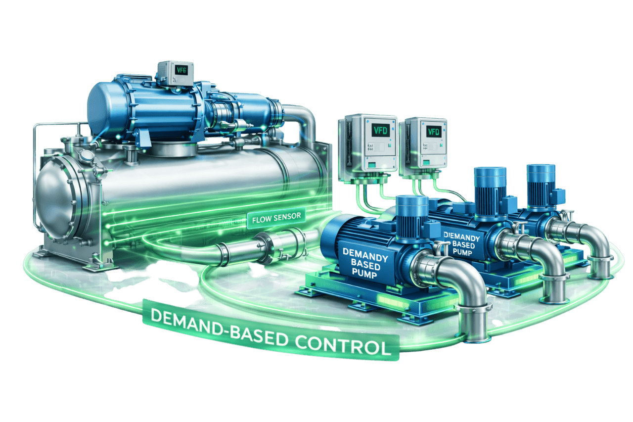
A VFD on its own is just a speed-changing device. A "variable speed" pump needs the right sensor location, setpoint, staging logic and commissioning. Without them, it often runs close to full speed all day and delivers only a fraction of the savings it promised. That is why Compress India treats demand-based pumping as an engineering and execution project, not a product sale.
Our HVAC execution team brings hydraulics, controls and electrical work under one roof:
- 1. Site survey & data logging: we record pump power, flow, differential pressure and operating hours before any design decision.
- 2. Hydraulic review: we assess the system curve, pump curves, index circuit and valve types.
- 3. Strategy selection: we choose the right mix of DP control, setpoint reset, pump staging and chiller plant optimization.
- 4. Engineering: we select pumps, VFDs, sensors, valves and pump control panels, backed by detailed drawings.
- 5. Installation: we plan the work around your operations, including night and weekend shutdowns.
- 6. Commissioning & tuning: we tune control loops, verify staging and optimize setpoints.
- 7. M&V and AMC: we measure the savings and sustain them over the life of the plant.
One team and one point of responsibility, from the first pressure reading to the last trend report.
What Is a Demand-Based Pump Control System?
What is demand-based pump control? A demand-based pump control system is an automatic pump control arrangement that continuously adjusts pump speed and the number of pumps in operation. The system delivers only the flow and pressure that the connected loads need at that moment.
At the simplest level, a booster pump with pressure switch or a portable pressure pump works on and off. The motor starts at a cut-in pressure and stops at a cut-out pressure. Demand-based pumping goes much further. A variable frequency drive pump does not switch between "full on" and "off", and it does not run flat out while valves throttle the excess. Instead, it modulates its speed smoothly in response to real-time signals from differential pressure, flow, temperature or valve position sensors.
The result is true pump control based on demand. It is also known as variable speed pump control, VFD pump control, a variable speed drive pump system or an intelligent pump control system. In HVAC chilled water and hot water systems, it is the foundation of efficient variable flow pumping.
Why Demand-Based Pump Control Is Important in Chilled Water Systems
Cooling loads change constantly with weather, occupancy, solar gain, shift patterns and time of day. Yet pumps, chillers and pipework are sized for peak design conditions, usually with safety margins added at every stage. The result is a pumping system that is oversized for most of its operating life.
In chilled water systems, fixed-speed pumping leads to:
- Over-pumping: far more water circulates than the coils actually need.
- Low delta-T: excess flow returns to the plant colder than design, which forces extra chillers and pumps online to carry the same load.
- Control problems: high differential pressure forces control valves to work nearly closed, which causes hunting, noise and poor comfort.
- High operating cost: this is especially true in plants running 24×7, such as hospitals, data centers and process facilities.
Why use variable speed pumps? Pump power falls steeply as speed drops, so even moderate speed reductions deliver large energy savings. Many facilities in Mumbai and across India need cooling for most of the year and pay commercial or industrial tariffs. For them, demand-based pump control is one of the most cost-effective energy efficiency upgrades available in the plant room. Energy codes such as ECBC and ASHRAE 90.1 also push new hydronic systems firmly towards variable flow.
How a Demand-Based Pump Control System Works
How does VFD pump control work in practice? A demand-based system runs as a continuous closed loop around the clock: it measures, compares, adjusts and optimizes.
1. Measuring Actual System Demand
As cooling coils need less chilled water, their two-way control valves begin to close, and the differential pressure across the distribution system rises. Differential pressure transmitters at the critical (index) circuit capture these changes. Flow meters, supply/return temperature sensors and valve position feedback add to the picture. Together they give the controller an accurate view of real-time demand.
2. Sending Signals to the Pump Controller / BMS
Sensor signals travel to a PLC, DDC controller or the building management system, typically as 4–20 mA signals or over BACnet/Modbus. A PID control loop compares the measured value, such as differential pressure at the index circuit, with the active setpoint. It then calculates the correction required.
3. Adjusting Pump Speed Through VFDs
The controller sends a speed command to the VFD drives for pumps. The drive changes motor frequency, and therefore pump speed, within configured minimum and maximum limits and ramp rates. Lower demand means lower speed, lower flow and dramatically lower power. This is pump speed control with VFD in its most practical form.
4. Staging Pumps On and Off Based on Load
In multi-pump plants, pump staging control decides how many pumps should run. When the running pumps approach maximum speed and still cannot hold setpoint, the next pump starts. When load falls enough for fewer pumps to cope efficiently, one pump stops. Time delays and hysteresis prevent short-cycling.
5. Continuous Setpoint Optimization
The best systems don't hold a fixed setpoint. Differential pressure setpoint reset logic lowers the setpoint whenever no control valve is close to fully open. It raises the setpoint as soon as a zone starts running short. This captures additional savings while every zone stays satisfied.
Main Components of a Demand-Based Pump Control System
A pump control system is only as reliable as its weakest component. A typical demand-based installation includes:
| Component | Role in the System |
|---|---|
| Pumps selected for variable speed duty | End-suction, split-case or vertical inline pumps that stay efficient across the operating range |
| IE3 / IE4 motors | High-efficiency, inverter-duty motors suitable for VFD operation |
| VFD drives for pumps | Vary motor frequency and pump speed in response to demand |
| Pump control panel / VFD panel | Houses VFDs, PLC or DDC controller, protection, metering and communication |
| Local control panel for pump (LCP) | Hand-Off-Auto selection, emergency stop and status indication at the pump |
| Pump motor starter panel (bypass) | DOL or star-delta starter for bypass or emergency operation where specified |
| Differential pressure transmitters | Measure system demand at the index circuit |
| Flow meters | Measure actual flow for staging, minimum flow protection and M&V |
| Temperature sensors | Monitor supply/return temperatures and delta-T |
| Two-way valves / PICVs | Allow true variable flow at coils and terminal units |
| Minimum flow bypass valve | Protects chillers in variable primary flow systems |
| Harmonic filters / line reactors | Keep power quality within acceptable limits |
| Energy meters | Record kW and kWh for performance tracking |
| BMS / chiller plant manager | Supervisory control, trending, alarms and remote pump monitoring |
Pump Affinity Laws & Energy Savings Principle
The savings from demand-based pumping come from the pump affinity laws. These describe how a centrifugal pump's flow, head and power change with speed.
Flow, Head and Speed Relationship
For the same pump and impeller:
- Flow varies directly with speed (Q ∝ N)
- Head varies with the square of speed (H ∝ N²)
- Power varies with the cube of speed (P ∝ N³)
A pump running at 80% speed therefore delivers about 80% of its flow at roughly 64% of its head.
Power Reduction at Reduced Pump Speed
Because power follows the cube of speed, small speed reductions produce large power reductions:
| Pump Speed | Flow | Head | Theoretical Power |
|---|---|---|---|
| 100% | 100% | 100% | 100% |
| 90% | 90% | 81% | 73% |
| 80% | 80% | 64% | 51% |
| 70% | 70% | 49% | 34% |
| 60% | 60% | 36% | 22% |
| 50% | 50% | 25% | 12.5% |
Real HVAC loops fall short of the pure cube law for two reasons. The pump must still maintain a minimum differential pressure at the index circuit, and motor and VFD efficiencies change slightly at low load. The savings remain substantial. This is exactly why correct DP sensor location and setpoint reset matter: they move the pump's operating curve closer to the true system curve and capture more of the theoretical savings.
Types of Demand-Based Pump Control Strategies
There is no single "best" logic for every plant. The right choice among pump control strategies in HVAC depends on your system configuration, instrumentation, BMS capability and budget.
Constant Differential Pressure Control
The VFD holds a fixed differential pressure setpoint. This method is simple, robust and widely used. However, when the sensor sits near the pumps, the setpoint must be high enough to satisfy the farthest coil at full load, which limits savings at part load.
Differential Pressure Setpoint Reset Control
The DP setpoint moves between a minimum and a maximum value based on load, time schedule, outdoor conditions or valve positions. This form of pressure reset control typically adds meaningful savings over a fixed setpoint. It requires only a modest increase in control complexity.
Remote / Index Circuit DP Control
The DP transmitter is installed at or near the hydraulically most remote or most demanding circuit, known as the index circuit. The setpoint no longer has to cover piping losses between the pumps and that circuit, so a much lower setpoint can be used. Large or branched systems may use several remote sensors, with the controller acting on whichever one is furthest below its setpoint.
Flow-Based Pump Control
Pump speed is controlled to deliver a target flow measured by flow meters. This approach is common in primary loops, where flow must track the chillers in operation and stay above minimum evaporator flow. It also suits process systems with predictable flow requirements.
Delta-T (Temperature Difference) Based Control
The pump modulates to maintain a target temperature difference between supply and return water. It works well in some condenser water, heating and process loops. In chilled water distribution, delta-T responds slowly and can starve individual loads. We therefore typically use it as a supervisory or reset input rather than the sole control variable.
Valve Position–Based Reset (Critical Zone Reset)
The BMS monitors the position of every major control valve. If no valve is nearly fully open, the DP setpoint is trimmed down. If one or more valves approach full open, the setpoint is raised. Critical zone reset keeps the system at the lowest pressure that still satisfies every zone, which makes it one of the most energy-efficient strategies available.
Proportional & Quadratic Pressure Control
The pump's head setpoint changes automatically with flow. In proportional pressure mode it follows a straight line; in quadratic pressure mode it follows a curve that mimics the system curve. These modes are often built into integrated pump-VFD units. They suit heating circuits, smaller chilled water loops and systems without remote sensing.
Sensorless Pump Control
Sensorless pump control estimates flow and head without a field DP transmitter. It uses the pump's stored performance map together with the drive's speed and power data. This reduces instrumentation and wiring, which makes it attractive for retrofits and compact plant rooms. Accuracy depends on the pump data and the operating region.
Comparison Table – Pump Control Strategies
| Strategy | Main Control Signal | Energy Savings Potential | Control Complexity | Best Suited For |
|---|---|---|---|---|
| Constant DP (near pumps) | DP at the plant | Moderate | Low | Small, simple systems |
| DP setpoint reset | DP + load/schedule | Good | Medium | Most chilled water secondary systems |
| Remote / index circuit DP | DP at critical circuit | Good to high | Medium | Large or long distribution networks |
| Flow-based | Flow meter | Moderate to good | Medium | Primary loops, process cooling |
| Delta-T based | Supply/return temperature | Variable | Medium | Condenser, heating and process loops |
| Valve position reset | Valve positions via BMS | Highest | High | Buildings with DDC valves and a capable BMS |
| Proportional / quadratic | Pump's internal estimate | Moderate to good | Low | Heating and smaller circuits |
| Sensorless | Pump map + VFD data | Moderate to good | Low to medium | Retrofits, integrated pump-VFD units |
Demand-Based Control by Pump System Type
Chilled Water Primary Pumps
In constant primary systems, primary pumps maintain steady flow through each chiller. Here, a VFD is often used as a fixed-speed "electronic balancing" device instead of a throttled valve. In variable primary flow systems, primary pumps modulate on differential pressure. Flow meters and a bypass protect each chiller's minimum evaporator flow and rate-of-change limits.
Chilled Water Secondary Pumps
Secondary pumps serving the building distribution are the classic application and often the most rewarding one. With two-way valves at the coils and remote DP control with setpoint reset, secondary pumps can spend most of the year well below full speed.
Condenser Water Pumps
Condenser water pumps traditionally run at constant flow. Demand-based options include trimming pump speed to the true design flow, or varying condenser flow in step with chiller loading. Either way, flow must stay within chiller minimum condenser flow and cooling tower minimum flow limits. We also interlock tower water treatment equipment, such as a dosing pump controller or peristaltic pump controller, with condenser flow status. Chemicals are then dosed only when water is circulating.
Hot Water / Heating Pumps
Heating hot water systems in hospitals, hotels, pharmaceutical plants and heat pump installations benefit from the same DP or proportional pressure control used in chilled water. For domestic hot water circulation, an aquastat for recirculation pump duty or temperature-based speed control can run the recirculation pumps. This saves energy while keeping hot water available at the outlets.
Process Cooling Pumps
Process loads such as moulding machines, compressors, reactors and test rigs often need stable header pressure or supply temperature rather than a building-style DP setpoint. We apply constant pressure pump control at the process header, with VFDs and minimum flow protection for heat exchangers. This keeps process conditions steady while cutting pumping energy during partial production.
Demand-Based Pump Control in Different Chilled Water Configurations
Constant Primary – Variable Secondary Systems
Constant-flow primary pumps serve the chillers while variable-speed secondary pumps serve the building, with a decoupler (common pipe) between the two. This is a proven, forgiving arrangement. The key risk is secondary flow exceeding primary flow. That causes reverse flow in the decoupler, warmer supply water and low delta-T, which correct secondary control and valve selection prevent.
Variable Primary Flow Systems
A single set of VFD pumps circulates water through both the chillers and the building. Variable primary flow (VPF) systems save pump energy, equipment and plant room space. They also demand careful design: chiller minimum flow, maximum rate of flow change, bypass valve sizing and accurate flow measurement are all critical.
Primary–Secondary Variable Flow Systems
Both primary and secondary pumps have VFDs. Secondary pumps respond to building DP, while primary pumps track secondary flow. Primary flow is typically kept slightly higher so there is a small forward flow in the decoupler. This captures savings on both circuits while keeping the chillers well protected.
Distributed Pumping Systems
In distributed pumping, variable-speed pumps at each building, zone or AHU draw only the water they need from a low-pressure main loop. This approach is popular in campuses and district cooling networks. It avoids over-pressurizing the network and can significantly cut throttling losses across large systems.
Sensors & Instrumentation for Demand-Based Pump Control
Good control starts with good measurement. Compress India specifies, installs and calibrates instrumentation that gives your controller an accurate, stable picture of the system.
Differential Pressure Transmitters
We use wet-to-wet DP transmitters with ranges matched to the working setpoint, never grossly oversized. Valve manifolds allow safe isolation and calibration, and the transmitters provide stable 4–20 mA outputs. We set signal damping to filter turbulence without slowing the control response.
Flow Meters
Electromagnetic flow meters offer high accuracy for staging and minimum flow protection. Insertion and clamp-on ultrasonic meters are practical for retrofits where cutting into the pipe isn't possible. We respect straight-run requirements so readings stay reliable.
Temperature Sensors
Immersion sensors in thermowells ensure accurate delta-T measurement, ideally as matched pairs for supply and return. Even small temperature errors distort delta-T and load calculations, so sensor quality matters.
Valve Position Feedback
Actuator feedback signals mapped into the BMS make critical zone reset possible. We verify that the feedback reflects the actual valve position, not merely the command signal sent to the actuator.
Sensor Location & Calibration
Where to install the differential pressure sensor is one of the most important decisions in the entire design. The DP sensor should sit across supply and return at or near the most remote or hydraulically most demanding coil, not across the pump. Every sensor is calibrated at commissioning and checked periodically, because a drifting DP transmitter can quietly erase your savings.
Multi-Pump Staging in Demand-Based Systems
Parallel Pump Staging Logic
A well-designed sequence adds a pump when two conditions hold: the running pumps have exceeded a high-speed threshold, commonly around 90–95%, for a set time, and the setpoint still isn't met. A pump is removed when the remaining pumps can comfortably carry the load. Time delays, hysteresis and minimum run times prevent frequent starts and stops.
Best Efficiency Point (BEP) Based Staging
Advanced pump staging control compares each pump's operating point with its best efficiency point. Two pumps at moderate speed can consume less power than one pump near full speed. BEP-based staging captures that difference and maximizes wire-to-water efficiency.
Equal Speed Operation of Parallel Pumps
Identical pumps running in parallel should operate at the same speed. If one pump runs slower, it can be pushed back towards its shut-off head, leading to overheating, internal recirculation and vibration. Our control sequences keep parallel pumps speed-matched at all times.
Minimum Speed Limits
Every VFD pump controller needs a sensible minimum speed. The limit maintains motor cooling, keeps the pump above its minimum continuous stable flow and respects chiller minimum flow. On 50 Hz systems it is commonly set around 20–30 Hz. The right value is always derived from actual pump, motor and system data.
Duty–Standby Rotation
Alternating pump controller logic rotates the lead pump by run hours so wear is shared evenly. It also changes over to the standby pump automatically on any fault. For two-pump sets, a dual pump control panel with a duplex alternating pump controller delivers the same reliability on a smaller scale; this is also called a duplex pump control panel.
Integrated Pump & Chiller Plant Optimization
Pumps don't operate in isolation. The lowest-cost plant is the one that minimizes total plant energy across chillers, pumps and cooling towers together.
Pump and Chiller Energy Trade-Off
Lower flow saves pump energy. If it reduces chiller efficiency or forces extra chillers online, though, the net result can be negative. We tune pump and chiller sequences together and use total plant kW/TR as the performance measure, not pump kW alone.
Chilled Water Supply Temperature Reset
Raising chilled water supply temperature at part load improves chiller efficiency. However, it can increase required flow and pump energy, and it must respect dehumidification needs. A carefully tuned reset strategy balances both sides of the equation.
Condenser Water Flow Optimization
Reducing condenser water flow cuts pump energy but raises condensing temperature and chiller lift. Optimized condenser flow, combined with smart cooling tower fan control, finds the point where combined chiller, pump and tower energy is lowest.
Benefits of Demand-Based Pump Control Systems
Significant Pumping Energy Savings
Pump energy savings with VFD control are among the most dependable in building services. Systems with genuine load variation commonly cut pumping energy by around 30–50%. Savings can go higher where existing pumps were heavily throttled or bypassed.
Reduced Over-Pumping and Low Delta-T
Delivering only the flow the coils need helps restore design delta-T. Chillers then load properly, and extra chillers and pumps don't run unnecessarily.
Stable System Pressure & Better Comfort Control
Controlled, moderate differential pressure lets control valves modulate in their ideal range. This improves temperature control and comfort in every zone.
Lower Noise and Valve Wear
Excess pressure across nearly closed valves causes whistling, cavitation and seat wear. Lower system pressure means quieter operation and longer valve life.
Longer Pump and Motor Life
Running at lower speeds reduces bearing loads, seal wear and vibration. This extends the life of pumps and motors and stretches the intervals between overhauls.
Soft Start and Reduced Electrical Stress
VFDs ramp motors up smoothly. This eliminates the high inrush current, mechanical shock and water hammer associated with direct-on-line starting.
Real-Time Monitoring & Data Insights
Integrated with your BMS or a remote pump monitoring system, demand-based systems provide live data on speed, power, flow, pressure and alarms. Where required, IoT gateways add remote and wireless pump control and monitoring. Your team can then see plant performance from a phone or laptop.
Want to know what these benefits are worth in your plant? Ask Compress India for a pump energy assessment.
Limitations & Design Challenges
Demand-based pumping delivers excellent results when it is engineered properly. Being upfront about the challenges is part of how we get it right.
Incorrect Sensor Location
A DP sensor placed across the pumps or too close to the plant forces a high setpoint and wipes out much of the potential savings. A sensor placed on a non-critical branch can starve remote zones.
Poorly Tuned Control Loops
Factory-default PID settings rarely suit a real system. Poor tuning causes pressure swings, speed hunting and unnecessary wear on VFDs, valves and actuators.
Minimum Flow Requirements of Chillers
Chillers need minimum evaporator and condenser flow, and many limit how quickly flow can change. Variable flow designs must protect these limits with flow measurement, bypass control and ramp-rate limits.
Control Complexity & Commissioning Requirements
More sensors, sequences and interlocks demand disciplined commissioning and trained operators. If commissioning is skipped, even a well-designed system will underperform.
Initial Cost of VFDs and Instrumentation
VFDs, sensors, valves and controls require upfront investment. In systems with genuine load variation, the energy savings usually repay this within a few years. That is why we estimate savings before recommending any investment.
Harmonics & Power Quality Considerations
VFDs draw non-linear current that introduces harmonic distortion. Without mitigation, this can overheat transformers, disturb sensitive equipment and breach utility limits. Line reactors, DC chokes and harmonic filters address this at the design stage.
Demand-Based Pump Control vs Constant Speed Pumping
Here is how constant speed vs variable speed pumps compare in day-to-day operation:
| Parameter | Constant Speed Pumping | Demand-Based Pump Control |
|---|---|---|
| Pump speed | Fixed at 100% | Varies with actual demand |
| Energy use at part load | High, because excess pressure is throttled or bypassed | Low, because power follows the affinity laws |
| Flow control method | Three-way valves, bypasses or throttling | Two-way valves/PICVs with VFD speed control |
| Delta-T performance | Often low at part load | Held closer to design |
| Starting method | DOL/star-delta with high inrush | Soft start through the VFD |
| Noise and valve wear | Higher | Lower |
| Monitoring | Basic run/trip status | Speed, power, flow, pressure, alarms and trends |
| Upfront cost | Lower | Higher |
| Lifecycle cost | Higher | Lower |
Demand-Based Pump Control vs Throttling Valve Control
Throttling a discharge valve to reduce flow is like driving with the accelerator floored while pressing the brake. The pump still runs at full speed; the valve simply adds resistance, and the pump rides back along its curve. Power falls only slightly because the pump keeps producing high head, and most of that head is lost across the valve as heat, noise and wear.
With a VFD, the pump slows down instead. Flow and head drop together, and power falls sharply in line with the affinity laws. For the same reduced flow, VFD speed control typically uses a fraction of the power of throttling. That is why one of the first steps in many retrofits is to open throttled discharge and triple-duty valves fully and let the VFD do the work.
Sensor-Based vs Sensorless Demand-Based Pump Control
| Parameter | Sensor-Based Control | Sensorless Control |
|---|---|---|
| Demand signal | Field DP transmitters, flow meters, valve feedback | Pump map plus VFD speed and power data |
| Installation effort | Sensor tapping, cabling and calibration | Minimal field instrumentation |
| Accuracy | High, when sensors are well located and calibrated | Good within the pump's mapped operating region |
| Setpoint reset and valve-based optimization | Fully supported | Limited; usually follows a fixed control curve |
| Best suited for | Large, branched and complex plants | Retrofits, compact systems, integrated pump-VFD units |
| Maintenance | Periodic sensor calibration | Few field devices to maintain |
A hybrid approach often works best. Individual pumps run sensorless or proportional control, while remote DP sensing and BMS-level reset logic provide supervisory optimization.
ECBC & ASHRAE 90.1 Considerations for Variable Speed Pumping
India's Energy Conservation Building Code (ECBC) and ASHRAE Standard 90.1 both steer hydronic systems towards variable flow. Exact requirements depend on the edition and compliance path that apply to your project. The provisions that matter for pumping typically cover:
- Variable flow design: systems whose control valves modulate with load should be able to reduce pump flow substantially at part load, subject to equipment minimum flows.
- Variable speed drives on larger pump motors: these make pump power drop sharply as flow reduces. ASHRAE 90.1 has long used a benchmark of no more than about 30% of design pump power at 50% of design flow.
- Sensor location: differential pressure is measured at or near the most remote or most demanding heat exchanger.
- Setpoint reset: where DDC controls are available, the DP setpoint is reset based on valve position.
- Efficient equipment: efficient pumps and high-efficiency motors are expected, with tighter requirements at ECBC's higher compliance levels (ECBC+ and SuperECBC).
Compress India designs demand-based pumping systems that support code compliance and green building documentation. We work alongside your MEP consultant to align control sequences with the specific requirements of your project.
Demand-Based Pump Control Systems for HVAC
For commercial and institutional buildings, Compress India delivers demand-based pump control across the complete HVAC hydronic system. This covers chilled water primary and secondary circuits, condenser water, heating hot water and AHU/FCU distribution loops.
Every project includes a clearly documented chilled water pump control sequence. It covers start/stop, staging, setpoint reset, minimum flow protection, alarms and failure modes, so your operators and BMS team know exactly how the plant should behave. You may be planning a new chiller plant or a VFD retrofit for chilled water pumps in an existing building. Either way, the goal is the same: lower pumping energy, stable comfort and a plant that is easy to operate.
Demand-Based Pump Control Systems for Industrial & Process Cooling
Industrial plants need cooling water they can depend on. Our demand-based solutions for process cooling cover process chilled water loops, cooling tower circuits, compressor and machine cooling, and utility water systems. Each is built with the redundancy and stability that production demands.
Here the priorities shift to stable header pressure, tight supply temperature, heat exchanger minimum flow and seamless integration with process PLCs. Variable frequency drive water pump systems with constant pressure or temperature-based control keep process conditions steady at full output. They also deliver meaningful savings during partial production, weekends and seasonal lows.
Applications of Demand-Based Pump Control Systems
Commercial Buildings & Office Complexes
Office loads swing with occupancy, hybrid working patterns, after-hours use and weekends. Demand-based pumping cuts energy the moment floors empty out, without compromising comfort when they fill up again.
Shopping Malls
Long operating hours, anchor stores, food courts and multiplexes create highly variable loads through the day. Variable flow pumping matches that profile and trims operating costs across thousands of running hours.
Hospitals
Operating theatres, ICUs and patient areas need cooling and heating 24×7. We design demand-based systems for hospitals with N+1 pumps, redundant sensors and fail-safe fallback modes, so reliability is never traded for savings.
Data Centers
Continuous, high-density cooling makes pump energy a constant cost. We combine demand-based control with redundant instrumentation, fail-safe speed on sensor loss and concurrent maintainability. This delivers efficiency without risking uptime.
Pharmaceutical Facilities
Cleanroom HVAC, process cooling and utility systems all benefit from demand-based pumping. In utility areas, we also bring supporting protections into the plant's monitoring. Examples include a reverse osmosis low pressure switch protecting RO high-pressure pumps in purified water systems and a vacuum pump controller for process vacuum.
Manufacturing Plants
Process cooling water, compressed air aftercoolers and machine cooling loops are ideal candidates for variable speed control. The same demand-based principle also applies to other plant utilities, from high flow hydraulic pump power packs to vacuum systems.
Hotels
Guest room loads vary with occupancy and time of day. Along with HVAC pumping, hotels benefit from VFD water pump boosting for pumped shower systems and from temperature-controlled hot water recirculation. The result is consistent guest comfort at lower running cost.
Airports & Metro Systems
Large terminals and underground stations run extensive chilled water networks with long pipe runs and fluctuating passenger loads. Remote DP control with multiple sensors and distributed pumping keeps every zone supplied efficiently.
IT Parks & Campuses
Multiple buildings served from a central plant need smart distribution. Distributed pumping or multi-sensor remote DP control keeps the farthest building satisfied without over-pressurizing the nearest one.
District Cooling Plants
In district cooling, pumping energy scales with network size. Distributed pumping, delta-T management at energy transfer stations and integrated plant optimization are essential to efficient, profitable operation.
System Design & Sizing
System Curve & Pump Curve Analysis
We plot the system curve and overlay pump curves at different speeds to see exactly where the pumps will operate across the load range. The aim is to keep pumps close to their efficient region for most operating hours, not just at the design point.
Design Flow & Head Calculation
Design flow is calculated from cooling load and delta-T: Flow (m³/h) = Load (kW) ÷ (1.163 × ΔT in °C). At a 5.5 °C delta-T, that works out to roughly 0.55 m³/h per TR. Designing for a higher delta-T reduces flow, pipe sizes and pump power. Pump head is the total friction loss through the index circuit, including pipes, fittings, chiller, coil, control valve, strainers and balancing devices. We apply sensible margins rather than stacked safety factors.
DP Setpoint Selection
The design DP setpoint equals the pressure drop required across the index circuit at design flow, plus a small margin. That pressure drop covers the coil, control valve and branch piping. We also define a minimum setpoint, so reset logic never drops below what the least-favoured zone needs at low load.
Minimum Flow & Minimum Speed Calculation
Minimum system flow is set by the highest of three limits: chiller minimum evaporator flow, pump minimum continuous stable flow and any heat exchanger requirement. Minimum pump speed is then derived using the affinity laws against the control curve. Where required, we also size a minimum-flow bypass.
Number of Pumps & Redundancy Selection
Common arrangements include 2 × 100% (duty/standby), 3 × 50% (two duty, one standby) and larger multi-pump sets. More pumps improve part-load efficiency and redundancy but add cost and space. Critical facilities typically require N+1 redundancy on both pumps and drives.
Pump & VFD Selection Criteria
Pump Selection for Variable Speed Operation
For variable speed service, we select pumps with the design point at or slightly to the right of the best efficiency point. As speed and flow reduce, the operating point then moves through the efficient region. We avoid oversized pumps, and we choose pumps for parallel operation with stable, steadily rising curves.
VFD Sizing and Selection
We size VFDs on motor full-load current rather than kW alone, rate them for variable torque duty and derate them for plant room temperature and enclosure conditions. We also consider IP rating for humid plant rooms, built-in pump functions, BACnet/Modbus communication, EMC filtering and bypass arrangements for critical systems.
IE3 / IE4 Motor Selection
IE3 (premium) and IE4 (super premium) efficiency motors, classified under IEC 60034-30-1 and IS 12615, reduce losses over the full operating range. Motors must be suitable for inverter duty. They also need adequate cooling at low speed and bearing current protection on larger frames.
Harmonic Filters & Line Reactors
Mitigation depends on VFD capacity and the electrical network. It ranges from line reactors and DC chokes to passive filters and active harmonic filters. Large loads may call for multi-pulse or active front end drives. We check designs against IEEE 519 guidance and utility requirements.
Integrated Pump–VFD Units
Integrated units mount the drive directly on the motor, saving panel space and cabling, and often include built-in sensorless control. They are a smart choice for the compact plant rooms common in Mumbai's high-rise buildings. Heat, humidity and serviceability must be properly considered.
Control Valve Selection for Demand-Based Systems
Two-Way Control Valves
Three-way valves divert water back to the return and keep flow constant, which defeats demand-based pumping. Two-way valves allow flow to fall with load, making them the essential foundation of any variable flow system.
Pressure Independent Control Valves (PICV)
PICVs combine a differential pressure regulator with a control valve. Each coil receives the correct flow regardless of pressure fluctuations elsewhere in the system. PICVs simplify balancing, improve delta-T, allow lower pump setpoints and make DP reset strategies far more effective.
Valve Authority & Sizing
Valve authority compares the pressure drop across the fully open valve with the total pressure drop of the circuit it controls. A value of around 0.5 is a common design target. Oversized valves operate nearly closed, causing hunting and poor control, so correct sizing is essential.
Controls, Automation & BMS Integration
The logic may run in a dedicated variable speed pump controller, a PLC or your BMS. Wherever it sits, the controls are what turn hardware into savings.
PLC / DDC Controller Programming
Our control programs cover pump start/stop, speed control, staging, duty rotation, setpoint reset, minimum flow protection, sensor failure handling and alarms. We document each sequence clearly and program it on the PLC or DDC platform that suits your site.
PID Loop Tuning
We tune proportional, integral and derivative settings on site under real operating conditions, using step tests and load changes. We configure output limits and anti-windup so the loop stays stable across the full operating range.
Trim & Respond Reset Logic
At fixed intervals, the controller counts "requests", for example valves that are more than 95% open. With few or no requests, it trims the setpoint down by a small step. When requests exceed a threshold, it raises the setpoint. The system continuously settles at the lowest setpoint that keeps every zone satisfied.
ASHRAE Guideline 36 High-Performance Sequences
ASHRAE Guideline 36 publishes standardized, high-performance sequences of operation for HVAC systems, built around proven logic such as trim & respond reset. We use these sequences as a reference framework and adapt them to Indian plant configurations, equipment and BMS platforms.
Chiller Plant Manager & BMS Integration
We integrate VFDs, sensors and pump control panels with your chiller plant manager and BMS over BACnet, Modbus or hardwired I/O. Chillers, pumps and cooling towers are then sequenced as one plant. BMS pump control screens give operators live graphics, trends and alarms.
Remote Monitoring & Energy Dashboards
Remote pump monitoring system dashboards display kW, kWh, kW/TR, speed, DP, flow, run hours and alarms, with SMS or email alerts. Facilities with utility tanks can add a water tank level monitoring and pump control system to the same dashboard. This gives you one view of every pump on site.
Energy Efficiency & Power Consumption
Pump energy efficiency is not about a pump's nameplate efficiency. It is about how much energy the system uses to deliver the cooling it needs. Here is how we calculate, estimate and verify it.
Pumping Energy Calculation
Pump input power can be estimated as:
Power (kW) = Flow (m³/h) × Head (m) ÷ (367 × overall efficiency)
For example, take a pump delivering 220 m³/h at 32 m head with a combined pump-motor efficiency of 73%. It draws about 26 kW. Running 4,000 hours a year at constant speed, that is roughly 1,04,000 kWh annually.
Energy Savings Estimation with VFDs
We estimate savings using a bin method: we multiply the hours at each load level by the pump power at that load under demand-based control. Here is an illustrative example for the pump above:
| Load (% of design flow) | Hours per Year | Approx. Power with Demand-Based Control | Energy (kWh) |
|---|---|---|---|
| 100% | 400 | 26.0 kW | 10,400 |
| 80% | 1,200 | 16.1 kW | 19,320 |
| 60% | 1,600 | 9.4 kW | 15,040 |
| 40% | 800 | 4.9 kW | 3,920 |
| Total | 4,000 | 48,680 |
Against the constant-speed baseline of 1,04,000 kWh, that is a saving of about 55,320 kWh, or around 53%. At an assumed tariff of ₹10 per kWh, that is roughly ₹5.5 lakh a year. The power values allow for a minimum control pressure and lower efficiency at reduced speed, so they are deliberately more conservative than the pure cube law. This example assumes the existing system runs at constant flow. Where two-way valves are already installed, the baseline is lower and so are the savings, which is why we always measure before we estimate.
Measurement & Verification (M&V)
We log baseline power, flow and pressure before the retrofit and measure them again afterwards under comparable conditions. Results are normalized for cooling load (TR-hours) and weather using an IPMVP-aligned approach. The savings you see are real, not assumed.
Return on Investment & Payback Analysis
Simple payback = project cost ÷ annual savings. Many well-suited retrofits pay back in roughly one to three years, and 24×7 facilities often recover their investment faster. Beyond energy, the return includes lower maintenance, longer equipment life, better comfort and potential chiller savings from improved delta-T.
Installation of Demand-Based Pump Control Systems
Compress India installs demand-based pump control systems with minimal disruption to your operations:
- 1. Shutdown planning: we phase cut-overs with your facility team and work nights and weekends where needed, so cooling stays available.
- 2. Pump control panel / VFD panel installation: we install panels in a dry, ventilated location with the right enclosure rating and heat management.
- 3. Power and control cabling: we use VFD-rated shielded motor cables with proper glanding and earthing, and we segregate power and signal cables.
- 4. Sensor installation: we fit DP tappings at the index circuit, flow meters with correct straight runs, and thermowells for temperature sensors.
- 5. Valve works: we convert three-way valves to two-way valves or PICVs and add minimum-flow bypass valves where required.
- 6. BMS and communication wiring: we handle network cabling, addressing and point mapping.
- 7. Pre-commissioning checks: we check insulation resistance, motor rotation, I/O and every point from end to end.
All work follows safe electrical practices, including permits and lockout/tagout.
Testing & Commissioning
Commissioning is where savings are either locked in or lost. Our commissioning process verifies every function before handover.
Sensor Calibration
We zero- and span-check DP transmitters, verify flow meters against reference measurements and compare temperature sensors with calibrated probes. The controller acts on accurate data from day one.
Control Loop Tuning & Stability Testing
We tune loops under real load with step changes, valve opening/closing tests and pump start/stop disturbances. The system must hold DP within tolerance without hunting before it is signed off.
Pump Staging Verification
We test stage-up and stage-down thresholds, lead-lag rotation, fault changeover, sensor failure fallback and restart behaviour after power failure. The plant then responds correctly to every scenario.
Setpoint Optimization
We field-verify the lowest DP setpoint that satisfies all zones at design and part load. We then set reset limits, document the final settings and train your operators on the complete sequence.
Maintenance & AMC for Demand-Based Pump Control Systems
A demand-based system keeps saving only if it keeps performing. Compress India's AMC for pump control systems can be comprehensive or non-comprehensive, and typically includes:
- VFD health checks covering cooling fans, heat sinks, DC bus capacitors, fault logs and parameter backups
- Calibration and verification of DP, flow and temperature sensors
- Trend reviews and setpoint re-optimization
- Pump and motor checks covering vibration, alignment, bearings, seals and insulation resistance
- Pump control panel thermography and checks on terminations, contactors and relays
- Harmonic and power quality checks
- Valve, actuator and PICV checks, plus strainer cleaning coordination
- Periodic energy performance reports
Common Problems & Troubleshooting
Pump Speed Hunting / Unstable Control
Speed and pressure oscillate continuously. Common causes include:
- aggressive PID gains
- a noisy DP signal
- a sensor too close to the pumps or fittings
- oversized control valves
- staging thresholds set too close together
Retuning, signal filtering, sensor relocation and wider hysteresis usually solve it.
Pumps Running at Full Speed Continuously
Typical causes include:
- an excessive setpoint
- a failed or disconnected DP sensor
- a VFD left in hand or bypass mode
- three-way valves or open bypasses
- stuck-open valves
- choked strainers or air in the system
A systematic check from sensor to valve pinpoints the cause.
Insufficient Flow at Remote Zones
The usual causes are a DP sensor on the wrong branch, a setpoint that is too low, balancing issues, air locks or partially closed isolation valves. Relocating or adding sensors, introducing critical zone reset and rebalancing restore flow.
DP Sensor Failure or Drift
A lost or drifting signal can drive pumps to maximum or minimum speed. Out-of-range alarms, a fail-safe fixed speed on sensor failure, periodic calibration and redundant sensors for critical facilities prevent this.
VFD Faults & Trips
Common trips include overcurrent, overvoltage, undervoltage, overtemperature and earth faults. Causes range from poor panel ventilation, dust and humidity to supply dips, long motor cables, harmonics and incorrect parameters. All of these can be corrected at the root.
Pump Operation Below Minimum Flow
When minimum speed is set too low or most valves close at night, pumps can overheat, recirculate and vibrate, and chillers may trip. Correct minimum speed, active minimum-flow bypass control and proper staging prevent it.
Low Delta-T
Low delta-T is caused by three-way valves, over-pumping, oversized or leaking valves, dirty coils, incorrect setpoints and open bypasses. Two-way valves or PICVs, DP reset, coil cleaning and valve audits bring delta-T back towards design.
Retrofitting Existing Pumping Systems with Demand-Based Control
Many buildings still run constant speed pumps installed years ago, often with throttled valves and three-way valves still in place. For these facilities, a demand-based retrofit is one of the fastest-payback energy projects available.
Adding VFDs to Constant Speed Pumps
Before adding VFDs, we check motor insulation and cooling suitability, the existing pump selection, panel space and harmonics. Often the first step is simply capping pump speed at the true design flow. Variable speed control then builds on that baseline.
Replacing Three-Way Valves with Two-Way Valves / PICVs
True variable flow requires two-way valves at AHUs and FCUs. Upgrading to PICVs goes a step further: it stabilizes flow, simplifies balancing and enables lower DP setpoints.
Adding DP Sensors & Flow Meters
We install remote DP sensors at the index circuits and use clamp-on flow meters to provide flow data with minimal disruption. This gives the new controls the signals they need.
Impeller Trim & Balancing Valve Review
We open throttled discharge and triple-duty valves fully so the VFD, not the valve, controls flow. We also review balancing valves. Grossly oversized pumps are corrected by capping maximum speed or, where appropriate, by impeller trimming.
Upgrading Controls & BMS Integration
New PLC/DDC sequences, BMS points and trends turn the retrofitted hardware into a genuinely intelligent pump control system. Many sites also run standalone controllers on utility pumps, for example:
- a Grundfos pump controller on a booster set
- a Pentek Intellidrive or Aquavar ABII constant-pressure drive
- a Multitrode pump controller in a sewage station
- a Lorentz solar pump controller or Rotosol solar pump controller on a borewell
- a CRI automatic pump controller, Mascontrol pump controller, Aquatech water level controller or Niagara automatic water pump controller on water tanks
Where these units are healthy and provide potential-free contacts or a communication port, their status and alarms can usually be brought onto the BMS rather than replaced.
Running constant speed pumps today? Talk to Compress India about a VFD retrofit assessment for your plant.
Demand-Based Pump Control System Cost in India
The cost of pump control varies enormously with scope. You may be comparing a 1 hp submersible pump control panel price, a 1.5 hp submersible pump control panel price or a submersible panel box price for a borewell. In that case you are looking at compact, standardized products. An engineered demand-based pump control system for a chiller plant is a different investment altogether. It involves hydraulic analysis, VFDs for large motors, instrumentation, valve changes, control programming and commissioning.
At plant scale, the right way to judge automatic pump control price is payback, not project cost alone. Compress India provides itemized estimates alongside projected savings, so you can see exactly what you invest and what you get back.
Factors Affecting Project Cost
- Number, size and type of pumps, and the VFD ratings required
- New pumps versus retrofit of existing pumps and motors
- Harmonic mitigation requirements
- Quantity and type of DP sensors, flow meters and temperature sensors
- Number of three-way valves to be converted to two-way valves or PICVs
- Pump control panel construction, enclosure rating and panel location
- PLC/DDC hardware, programming and BMS integration scope
- Cable routing distances and site access
- Shutdown constraints, night work and phasing requirements
- Commissioning, M&V and AMC scope
Information Required for a Quotation
To prepare an accurate proposal, please share as much of the following as possible:
- Pump schedule with make, model, flow, head, motor kW and speed for each pump
- Motor nameplate details and existing starter/panel type
- Chiller details, including minimum evaporator and condenser flows
- System schematic or P&ID showing the pumping configuration
- Type and quantity of control valves (two-way or three-way) at AHUs/FCUs
- Existing BMS make, controllers and communication protocols
- Operating hours and typical load profile
- Recent electricity bills or applicable tariff
- Electrical single-line diagram and available panel space
- Photographs of the plant room, pumps and panels
- Current problems, comfort complaints or energy targets
Don't have everything? Our engineers can collect the missing data during a site survey.
Demand-Based Pump Control System Contractor in Mumbai
Looking for a demand-based pump control system contractor in Mumbai? Compress India understands the realities of Mumbai's buildings:
- compact basement and terrace plant rooms
- high-rise pressure zones
- a humid coastal environment that is hard on panels and sensors
- strict shutdown windows in occupied commercial buildings
We support offices, malls, hospitals, hotels, data centers and industrial facilities across Mumbai, from BKC, Lower Parel, Worli and Andheri to Powai, Goregaon, Malad and Vikhroli. You may need a VFD pump retrofit, a BMS-integrated pump control panel or a complete chiller plant pumping upgrade. Our team handles each end to end.
Book a site survey with Compress India and find out how much your pumps could save.
Pump Control Solutions in Mumbai, Navi Mumbai, Thane & Maharashtra
Beyond chiller plants, most facilities run a wider network of pumps, and each one needs the right controller. Alongside HVAC demand-based pumping, Compress India supports facilities across the region. This includes Mumbai, Navi Mumbai (Vashi, Airoli, Mahape, Belapur and Taloja), Thane, Bhiwandi, Pune, Nashik and the rest of Maharashtra.
Water pressure boosting: Many buildings still rely on a booster pump with pressure switch or a basic motor pressure pump. Upgrading to a VFD-based pressure pump controller delivers true constant pressure pump control. A digital water pump pressure controller can also replace a worn mechanical water pump pressure control switch.
Submersible and borewell pumps: We provide the right submersible pump controller for each duty, from three-phase submersible pump starter panels down to single-phase units. Single-phase options include a single phase submersible pump control panel, also called a single phase submersible control panel, and a single phase submersible starter. We also supply:
- submersible pump control panels
- an automatic starter for submersible pump sets
- a digital control panel for submersible pump installations
- submersible pump control box options
- borewell automatic water controller units
Well pump control: We provide a correctly rated well pump control box for every motor, from a 1 hp well pump control box or 1.5 hp well pump control box to a 2 hp well pump control box. We also supply:
- submersible well pump control boxes
- well pump controllers with a digital well pump pressure switch
- wireless well pump control for remote borewells
Water level control: Options include a fully automatic water level controller for submersible pump systems and single phase water level controller and three phase water level controller options. We also supply submersible pump water level controllers and sump water level indicators. The best water level controller for your site depends on tank layout, pump type and power supply, and our team helps you choose.
Everyday water pump control: You may need an auto pump controller, an automatic water pump controller (often called a water auto controller), a water motor controller or a complete water pump control box. We match the controller for water pump duty to your site, including an automatic pump controller for water pump sets. We can also supply a water pump with controller as a single package.
Sump, drainage and sewage: We cover sump pump control panels and sump pump controllers, from a sump pump with internal float switch to duplex sets run by a duplex pump controller. We also supply sewage pump control panels, grinder pump control panels, simplex pump control panels and complete pump station control panels.
Local controls: We supply single phase control panels, a local control panel for pump sets, and a pump motor starter panel or starter panel for pump motors.
Fire pumping stations: Fire pumps follow their own statutory standards and approvals, so they stay separate from energy-optimization logic. However, a fire pumping station's run, fault and pressure status can be monitored on your BMS.
Demand-Based Pump Control Solutions Across India
Compress India takes up demand-based pump control projects across India. These range from Delhi NCR, Bengaluru, Hyderabad and Chennai to Pune, Ahmedabad, Kolkata and fast-growing industrial corridors. Our engineering process is standardized. The same survey methodology, hydraulic analysis, control sequence documentation and commissioning checklists apply wherever your facility is located.
Multi-site portfolios include retail chains, hospital groups, IT campuses and manufacturing networks. For them, remote pump monitoring and energy dashboards give the central team a consistent view of pump performance across every location. Our engineers support optimization both remotely and on site.
Why Choose Compress India for Demand-Based Pump Control Systems?
Hydraulic & Controls Engineering Expertise
Demand-based pumping sits where hydraulics, controls and electrical engineering meet. Our team works across all three, so pump curves, sensor locations and control logic are designed together rather than in isolation.
Complete Chiller Plant Integration
We look beyond the pumps to the whole plant, including chillers, cooling towers, valves and BMS. Pump savings are never achieved at the expense of chiller efficiency or comfort.
Pump, VFD & Sensor Selection Support
We help you select equipment based on your system's hydraulics and lifecycle cost. This covers everything from pump curves and VFD ratings to DP transmitter ranges and PICV sizing.
Control Sequence Programming & Tuning
We write, program and tune the sequences ourselves, covering DP control, setpoint reset, staging, rotation and failure modes. We document them clearly for your operators.
Installation & Commissioning
Our execution team installs panels, cabling, sensors and valves with careful shutdown planning. We then commission every loop and sequence before handover.
Retrofit & Energy Optimization
We upgrade existing plants by measuring the baseline, identifying the fastest-payback measures and verifying the savings after implementation.
AMC & Lifecycle Support
Calibration, trend reviews, VFD care and setpoint re-optimization keep your savings from drifting away, year after year.
How to Select the Right Demand-Based Pump Control Strategy
The right strategy depends on your system, not on a product catalogue. As a starting point:
- Small, simple loops with limited BMS: constant DP, proportional pressure or sensorless control
- Medium and large buildings with two-way valves: remote/index circuit DP control with setpoint reset
- Buildings with DDC valve feedback: valve position–based critical zone reset using trim & respond logic
- Constant primary plants: variable secondary pumping first, then variable primary flow where chillers and controls support it
- Campuses and district cooling: distributed pumping or multiple remote DP sensors
- Process cooling: header pressure or supply temperature control with minimum flow protection
- Hospitals and data centers: redundant sensors, fail-safe modes and N+1 pumps and drives
Not sure which fits your plant? A short site assessment will tell you which strategy fits and what it can save.
Get a Demand-Based Pump Control Solution from Compress India
Every month your pumps run at full speed is energy you won't get back. Compress India helps you capture those savings with a demand-based pump control system that one accountable team engineers, installs and supports.
Connect with Our HVAC Execution Team
Call our team or send an enquiry through this page with your pump schedule and plant details. Our engineers will review your system and recommend a site survey where needed. We will then prepare a clear proposal with projected savings and payback.
Related Systems Types & Components
Explore our comprehensive range of hydronic system configurations and components designed for efficient water distribution.
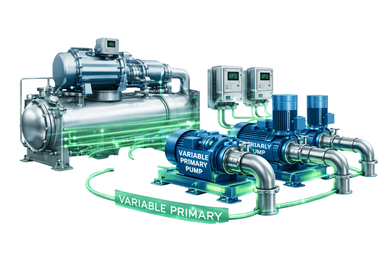
Variable Primary Flow Systems
Learn More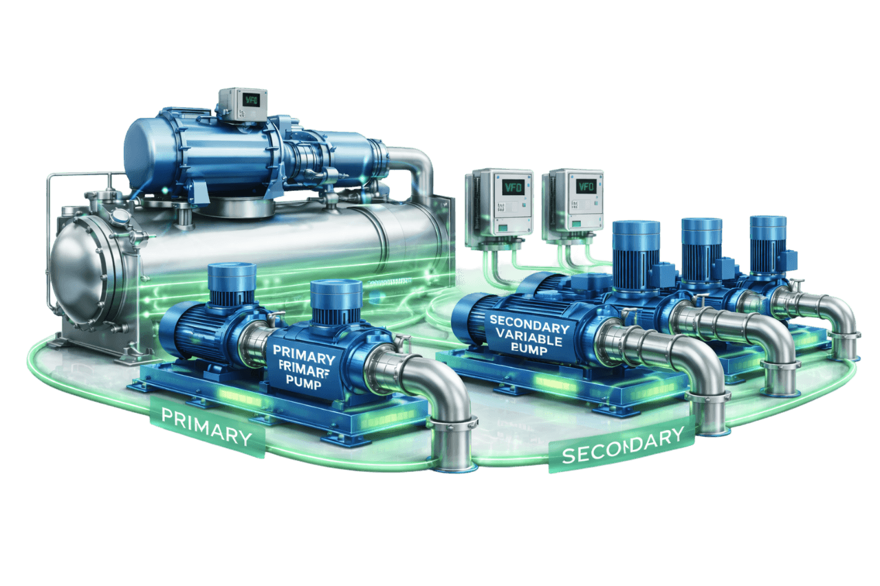
Primary–Secondary Variable Flow Systems
Learn More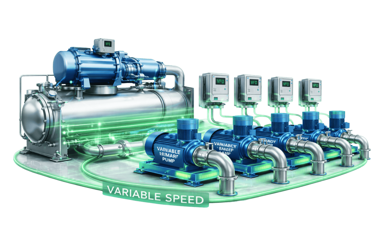
Multi-Pump Variable Speed Configurations
Learn More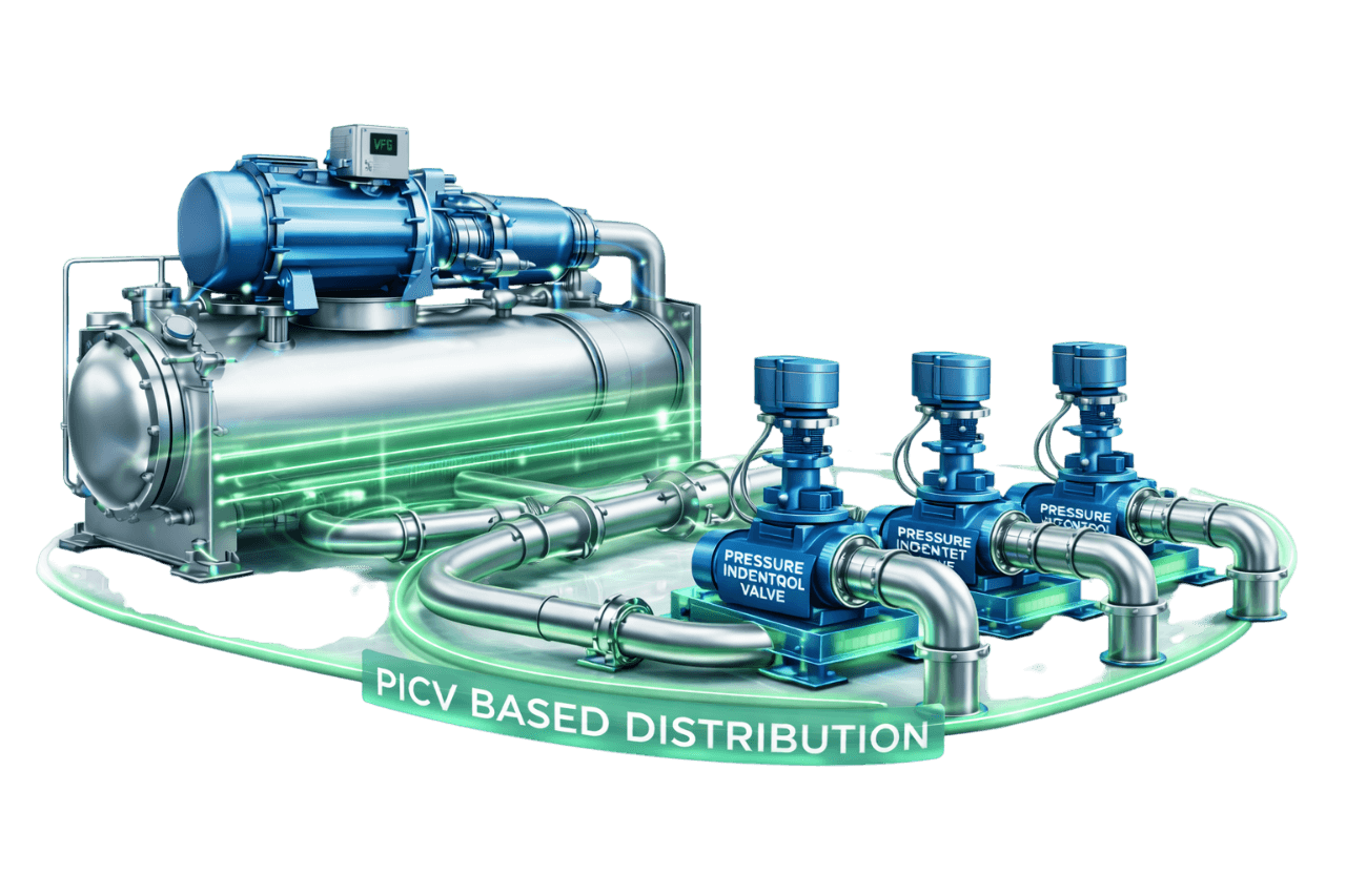
Pressure Independent Control Valve (PICV) Based Distribution
Learn MoreFrequently Asked Questions
Q1. What is a demand-based pump control system?
A demand-based pump control system automatically varies pump speed and the number of pumps running to match real-time system demand. It uses VFDs, sensors and a controller or BMS to deliver only the flow and pressure the loads need. This replaces running pumps at full speed and throttling the excess.
Q2. How does demand-based pump control work?
Sensors measure demand, usually differential pressure at the index circuit. A PID controller compares this with the setpoint and adjusts VFD speed accordingly. Pumps are staged on and off as load changes, and setpoint reset logic lowers system pressure whenever the zones allow.
Q3. How much energy can demand-based pump control save?
Savings depend on load profile, operating hours and the existing control method. In systems with genuine load variation, pumping energy reductions of around 30–50% are common. Savings can go higher where pumps were heavily throttled or bypassed. Compress India estimates savings from measured site data before recommending a solution.
Q4. What are the pump affinity laws?
The pump affinity laws state that flow varies with speed, head with the square of speed and power with the cube of speed. A pump at 80% speed theoretically needs only about half its full-speed power. In real HVAC systems savings are somewhat lower, because a minimum control pressure must still be maintained.
Q5. What is differential pressure control in pumping systems?
Differential pressure pump control maintains a set pressure difference between supply and return pipes, usually at a critical circuit. As valves close and DP rises, the VFD slows the pump. As valves open and DP falls, it speeds up. Every coil stays supplied with just enough pressure.
Q6. What is differential pressure setpoint reset?
Instead of holding a fixed DP setpoint, reset logic lowers it when demand is low and raises it when a zone needs more. It bases these changes on valve positions, load or schedules. A lower average setpoint means lower average pump speed and additional energy savings.
Q7. Where should the differential pressure sensor be installed?
Install it across supply and return at or near the most remote or hydraulically most demanding coil, known as the index circuit, not across the pump. Large or branched systems may need several sensors. The controller then responds to whichever circuit is furthest below its setpoint.
Q8. What is the difference between sensor-based and sensorless pump control?
Sensor-based control uses field DP transmitters and flow meters. Sensorless control estimates flow and head from the pump's performance map and VFD data. Sensor-based control offers higher accuracy and advanced reset options. Sensorless control needs less instrumentation and suits retrofits and compact systems.
Q9. What is delta-T based pump control?
Delta-T control varies pump speed to maintain a target temperature difference between supply and return water. It suits some condenser, heating and process loops. In chilled water distribution it is usually a supervisory or reset input. On its own, it can respond slowly and underserve individual loads.
Q10. What is trim and respond control logic?
Trim and respond is a reset method used in ASHRAE Guideline 36. The controller periodically trims the setpoint down by a small step when few zones need more. It raises the setpoint when enough requests arrive, such as valves nearly fully open. This way it continuously finds the lowest setpoint that satisfies the system.
Q11. How are multiple pumps staged in a demand-based system?
A pump is added when the running pumps reach high speed and still can't hold setpoint. It is removed when fewer pumps can carry the load efficiently, with delays and hysteresis to prevent cycling. Advanced logic stages around each pump's best efficiency point, keeps parallel pumps at equal speed and rotates duty by run hours.
Q12. Can demand-based control be used on condenser water pumps?
Yes, with care. Options include trimming pumps to the true design flow or varying condenser flow with chiller load, always within chiller and cooling tower minimum flow limits. Lower condenser flow can increase chiller energy. It should therefore be optimized on total plant energy rather than pump energy alone.
Q13. Is demand-based pump control suitable for data centers and hospitals?
Yes. Because these facilities run 24×7, their savings are often among the largest. Designs for critical facilities include:
- N+1 pumps and drives
- redundant sensors
- fail-safe speed on sensor loss
- VFD bypass where specified
- conservative minimum setpoints
Reliability is never compromised.
Q14. What is the minimum speed for pumps in a VFD system?
It depends on the pump, motor and system. On 50 Hz systems, minimum speed is commonly set around 20–30 Hz, which is roughly 40–60% speed. The correct value comes from motor cooling limits, the pump's minimum continuous stable flow and chiller minimum flow requirements.
Q15. Do demand-based systems need two-way valves or PICVs?
Yes. True variable flow requires two-way valves at the terminal units; three-way valves keep flow constant and cancel most of the savings. PICVs are recommended wherever possible because they stabilize flow, reduce balancing effort, improve delta-T and allow lower DP setpoints.
Q16. Can VFDs be added to existing constant speed pumps?
In most cases, yes. Compress India first checks motor insulation and cooling suitability, pump selection, panel space and harmonics. We then add VFDs, sensors and control logic. Throttled valves are opened and speed control takes over, often without replacing the pump itself.
Q17. What are common problems in demand-based pump control systems?
Common problems include:
- speed hunting
- pumps stuck at full speed
- starved remote zones
- sensor drift
- VFD trips
- operation below minimum flow
- low delta-T
Most trace back to sensor location, control tuning, valve issues or incomplete commissioning, and all are correctable.
Q18. What is the payback period of a demand-based pump control retrofit?
It depends on pump size, operating hours, tariff, load profile and project scope. Many well-suited retrofits pay back in roughly one to three years, and 24×7 facilities often recover their investment faster. We provide a site-specific payback estimate with every proposal.
Q19. What maintenance does a demand-based pump control system need?
Regular maintenance includes:
- VFD checks covering fans, heat sinks, capacitors and fault logs
- sensor calibration
- trend and setpoint reviews
- pump and motor mechanical checks
- panel thermography
- valve and actuator checks
A structured AMC keeps the system performing and the savings from drifting away.
Q20. What information is needed for a demand-based pump control system quotation?
We need:
- pump schedule and motor nameplates
- chiller details and minimum flows
- system schematic and control valve types
- BMS details
- operating hours and load profile
- electricity bills or tariff
- electrical SLD, panel space and plant room photographs
Our engineers can gather any missing data during a site survey.
Q21. Does Compress India design and install demand-based pump control systems?
Yes. Compress India provides complete demand-based pump control solutions for commercial, industrial and critical facilities in Mumbai, across Maharashtra and throughout India. Our scope covers:
- hydraulic analysis
- pump, VFD and sensor selection
- pump control panel engineering
- control programming and BMS integration
- installation and commissioning
- retrofits and AMC