Pressure Independent Control Valve (PICV) Based Distribution
(Design, Supply, Installation, Commissioning, Retrofit & Lifecycle Support for Chilled Water & Hot Water Distribution Systems)
PICV Based Distribution – Hydronic System Engineering & Execution
Every chilled water distribution system has the same weak point: the valves at the coils. When those valves are pressure dependent, the flow at each AHU and FCU changes whenever another valve opens or closes elsewhere in the building. Zones near the pumps get too much water and remote zones get too little. The plant pays for it with low delta-T, extra pumping and uncomfortable occupants.
Pressure Independent Control Valve (PICV) based distribution fixes the problem at its source. Each terminal unit gets a valve that regulates its own flow, whatever the pressure in the rest of the system. Compress India designs, supplies, installs and commissions PICV based chilled water distribution and hot water systems for commercial, healthcare, hospitality, data center and industrial facilities.
What we deliver:
- PICV system design, PICV sizing and valve schedules for new chilled water and hot water systems
- PICV valve selection and supply, with actuators and complete coil connection packages
- PICV installation, system flushing, flow presetting and commissioning
- Pump differential pressure control, setpoint reset and BMS integration
- Retrofits from three-way and conventional two-way valves, plus AMC support
Share your AHU and FCU schedule with Compress India for a PICV selection and savings review.
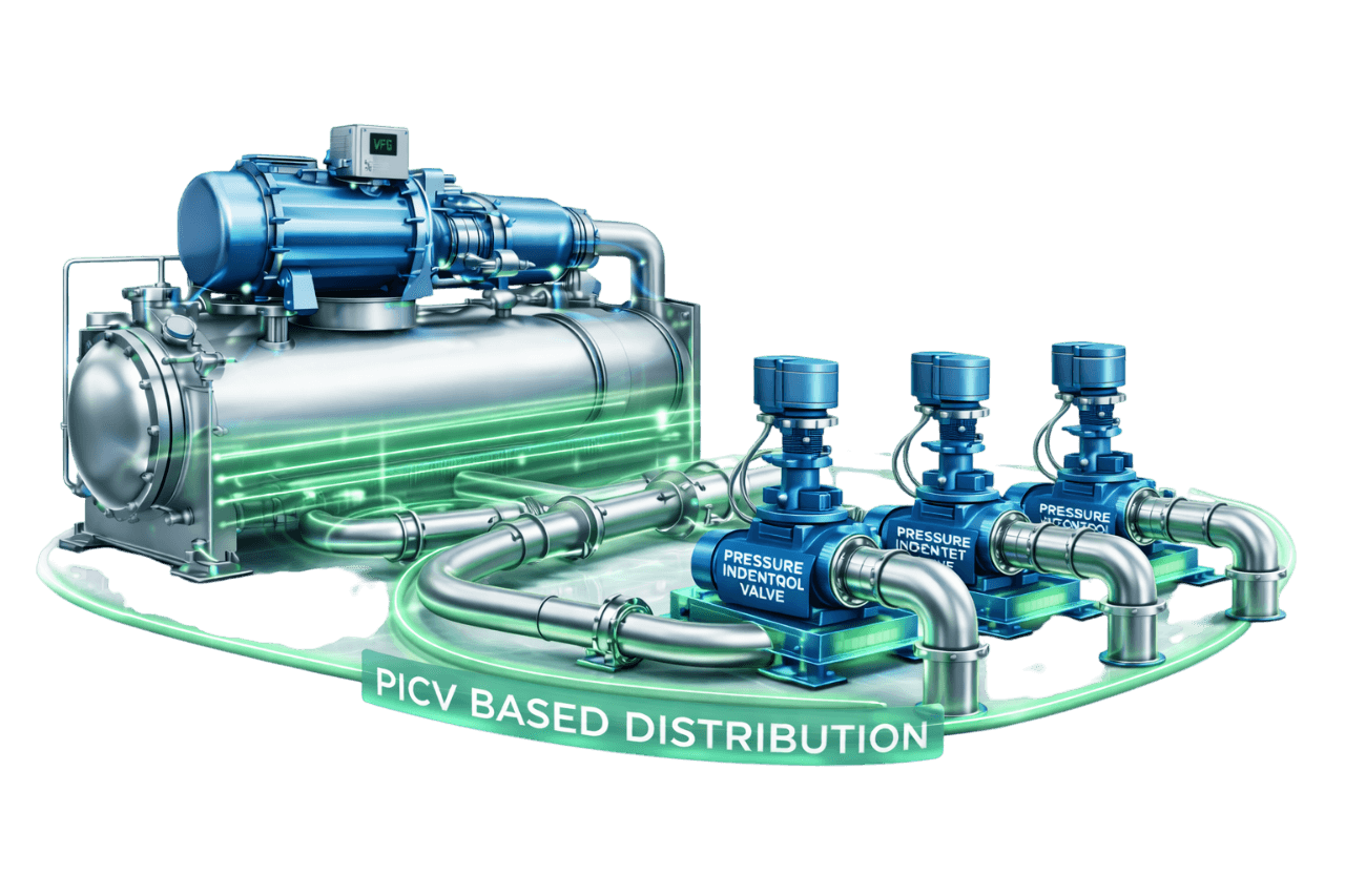
A PICV is a precise device, but it only performs as well as the system around it. Four conditions must all be met:
- The pumps must deliver enough differential pressure to the farthest valve.
- The water must be clean enough for the valve's small internal passages.
- Each valve must be preset to the right flow.
- Each valve must be wired to the right control signal.
Miss any one of these and even the best PICV underperforms.
That is why Compress India delivers each PICV based hydronic distribution system as a complete engineering and execution project:
- 1. Survey and data collection: we gather terminal unit schedules, coil data, piping layouts, pump details and BMS capability.
- 2. Hydronic design: we establish design flows, the index circuit, pump head and DP sensor location.
- 3. Valve selection: we define PICV type, size, flow range, actuator and connection kit for every terminal.
- 4. Supply coordination: we manage approved makes, datasheets, submittals and delivery schedules.
- 5. Installation: we install coil hook-ups, strainers, flushing bypasses, insulation and actuator wiring.
- 6. Flushing and commissioning: we clean the system, preset flows, verify differential pressure and optimize the pumps.
- 7. Lifecycle support: we provide trend reviews, maintenance, AMC and support for future expansion.
What Is a Pressure Independent Control Valve (PICV)?
A pressure independent control valve (PICV) is a 2 way pressure independent control valve that combines three functions in one body: a differential pressure regulator, an adjustable maximum flow limiter and a modulating control valve. The built-in regulator keeps the pressure across the control section constant. As a result, the flow through the valve depends only on its position, not on the pressure in the rest of the system.
A simple automatic flow regulating valve can only hold flow at a fixed maximum. A PICV valve also modulates that flow to match the load. In one component, it replaces a conventional two-way control valve, a manual balancing valve and a differential pressure regulator.
It goes by several names:
- PIBCV valve (pressure independent balancing and control valve)
- pressure independent balancing valve
- PICV flow control valve
- PICV balancing valve
Whatever the name, the PICV is the building block of the modern variable flow chilled water system.
What Is PICV Based Distribution in HVAC Systems?
PICV based distribution is an HVAC chilled water distribution approach in which every AHU, FCU or other terminal unit is controlled by its own PICV. The valves balance the system automatically at every load. Each valve modulates flow to match its coil's demand, while the pumps vary their speed to supply just enough differential pressure.
A PICV based HVAC distribution system needs no proportional balancing. It keeps flows correct at part load and delivers stable, energy efficient chilled water distribution. The same principle works for hot water heating and process loops, so a PICV based hydronic distribution system suits almost any building. Using a PICV in HVAC this way is now the benchmark for any variable flow HVAC system.
Problems with Conventional Pressure Dependent Control Valves
Conventional two-way and three-way control valves are pressure dependent. Their flow changes whenever the differential pressure across them changes, and in a real building that pressure changes constantly. The results are familiar to every facility team:
- Overflow near the pumps: valves close to the plant see high pressure and pass far more than design flow when open.
- Starved remote zones: valves at the end of long pipe runs cannot get enough flow during peak demand.
- Poor authority and hunting: as loads change, the pressure across each valve shifts, distorting its control and causing temperature swings.
- Balancing that doesn't last: manual balancing is correct only at full design flow. At part load, which covers most operating hours, flows drift.
- Low delta-T: overflowing coils return water too cold, forcing extra chillers and pumps to run.
- Rebalancing after every change: tenant fit-outs and extensions upset the balance and require expensive rework.
PICVs are designed to eliminate every one of these problems.
How a Pressure Independent Control Valve Works
Inside a PICV control valve, three functional sections work together to deliver stable flow.
1. Differential Pressure Regulator
A diaphragm and spring assembly senses the pressure before and after the control section. When system pressure rises, the regulator closes slightly; when it falls, the regulator opens. This keeps a constant differential pressure across the control section at all times.
2. Maximum Flow Presetting
The maximum flow is set on a presetting dial or, on some designs, through the actuator's stroke or maximum flow setting. Once preset to the terminal unit's design flow, the valve cannot exceed it. This prevents overflow at every coil.
3. Control Valve Section & Actuator
An actuator positions the control section, either a plug or a characterized ball, in response to the controller's signal. Because the pressure across the control section is constant, every actuator position corresponds to a predictable flow.
4. Constant Flow Despite System Pressure Changes
When other valves open or close, the pressure at this valve changes. The regulator absorbs the change within its working range, so the flow stays the same. This is pressure independent flow control in a chilled water system in its purest form.
5. Modulating Flow Based on Load Demand
When room or supply air temperature moves away from setpoint, the controller repositions the actuator. The PICV modulates between zero and its preset maximum, delivering exactly the chilled water flow control each coil needs.
How PICV Based Distribution Works Across the System
Variable Flow Distribution to Terminal Units
Every terminal unit draws only the water it needs. As loads fall, PICVs close down and total system flow drops. The building becomes a true variable flow chilled water system, from the coils back to the plant.
Automatic Dynamic Balancing
Each PICV holds its own flow regardless of what the other valves are doing. The result is automatic flow balancing across the whole building, at full load and at every part-load condition, without manual balancing valves.
Interaction with Variable Speed Pumps
As PICVs close, system differential pressure rises. A DP sensor detects the rise and the variable speed pumps slow down to hold setpoint. The PICVs keep flows correct while the pumps keep pressure just high enough, so each component does the job it is best at.
Response to Part-Load Conditions
Conventional systems drift out of balance at part load; a PICV chilled water system does not. Near and far valves both receive their correct flows, remote zones stay satisfied and return water stays warm. Delta-T is protected during the hours when the plant does most of its work.
Main Components of a PICV Based Distribution System
| Component | Role in the System |
|---|---|
| PICVs at each terminal unit | Regulate, limit and modulate flow to each coil |
| Actuators (on/off, modulating or smart) | Position each valve in response to the control signal |
| Coil connection packages | Isolation valves, strainers, unions, flexible hoses and P/T points around each PICV |
| Flushing bypasses | Allow pipework to be cleaned without passing debris through coils and valves |
| Variable speed pumps with VFDs | Supply differential pressure that follows demand |
| Differential pressure sensors | Provide the pump control signal from the index circuit |
| Minimum flow bypass at the plant | Protects chillers and pumps at very low system flow |
| Air and dirt separators | Remove air and debris that could affect valve performance |
| Water treatment and filtration | Maintain water quality over the life of the system |
| DPCVs on selected risers, where needed | Limit differential pressure where it could exceed valve ratings |
| BMS and controllers | Control temperatures, read valve positions and reset pump setpoints |
| Energy meters | Measure chilled water energy and verify savings |
Components of a PICV
Differential Pressure Regulator (Diaphragm & Spring)
This is the heart of the valve. A rubber diaphragm balanced by a spring responds to pressure changes and adjusts an internal regulating element. It keeps the differential pressure across the control section constant throughout the valve's working range.
Flow Presetting Element
A calibrated dial or adjustable orifice sets the maximum flow. Settings are usually marked as a percentage of nominal flow or as a flow value, and they can be locked against tampering.
Control Element / Valve Plug
The plug, cone or characterized ball modulates the flow. Its shape defines the valve's flow characteristic, typically linear or equal percentage.
Actuator
The actuator is the motor or thermoelectric drive that positions the control element. It receives on/off, analogue or digital commands. Smart versions also report position, flow and alarms to the BMS.
Pressure/Temperature (P/T) Test Points
Test points let commissioning engineers measure the pressure across the valve and confirm it is above the minimum operating differential pressure. On designs built for it, they also allow flow verification with the manufacturer's balancing instrument.
Types of Pressure Independent Control Valves
Mechanical PICV
The most common type. A mechanical diaphragm-and-spring regulator provides pressure independence, and a separate actuator controls the valve. Mechanical PICVs are reliable and cost-effective. They are available in sizes from small FCU valves to large flanged AHU valves.
Electronic PICV / Energy Valves
An electronic pressure independent valve measures flow directly with an integrated flow sensor. It adjusts its own position in a closed loop to hold the required flow. Energy valves add supply and return temperature sensors to calculate coil energy and manage delta-T, and they report all of this to the BMS over a network connection.
Characterized Ball-Type PICV
A ball valve with a characterizing disc provides the control function, paired with a mechanical pressure regulator. Characterized ball designs are compact and cover a wide flow range. They are popular on FCUs and small to medium AHUs.
Globe-Type PICV
A plug-and-seat design driven by a linear actuator. Globe-type PICVs offer precise modulation and good rangeability, and they are widely used on both FCUs and AHUs.
Flanged vs Threaded PICVs
Threaded PICVs cover smaller sizes, typically up to DN50, and suit FCUs and small AHUs. Flanged PICVs cover larger sizes for big AHUs, process heat exchangers and branch control. They are also easier to remove and service on large pipes.
Comparison Table – Mechanical vs Electronic PICV
| Parameter | Mechanical PICV | Electronic PICV / Energy Valve |
|---|---|---|
| Pressure independence | Mechanical diaphragm and spring | Closed-loop control using a flow sensor |
| Flow measurement | Not direct; verifiable with instruments on some designs | Direct, real-time flow reading |
| Delta-T monitoring | No | Yes, on energy valves with temperature sensors |
| Pressure requirement | Needs a spring start-up differential pressure | No spring start-up pressure; needs only the valve's own pressure drop at design flow |
| BMS data | Position feedback, or more with smart actuators | Flow, temperatures, energy and alarms |
| Cost | Lower | Significantly higher |
| Best suited for | FCUs and most AHUs | Large AHUs, critical loads, delta-T management |
PICV Actuator Types
The PICV actuator decides how the valve responds to your control system. Choosing the right PICV valve actuator is as important as choosing the valve itself. A PICV with actuator is supplied and tested as a matched pair.
On/Off Actuators
Motorized or thermoelectric on/off actuators open and close the valve under thermostat control. Because the PICV limits maximum flow, even on/off control delivers balanced flow. These actuators are common on FCUs in hotels, apartments and offices.
Modulating Actuators (0–10V / 4–20mA)
Modulating actuators position the valve anywhere between closed and fully open in response to an analogue signal: 0–10 V, 2–10 V or 4–20 mA. Most also return a position feedback signal. They are the standard choice for AHUs and FCUs that need precise temperature control.
Smart Actuators with BACnet / Modbus Communication
Smart actuators connect directly to the BMS over BACnet or Modbus. They receive commands and report valve position, actual or calculated flow, alarms and diagnostics. Some can also calculate energy when temperature sensors are added. They make critical valve reset logic much easier to implement.
Fail-Safe (Spring Return) Actuators
Fail-safe actuators drive the valve to a defined position, open or closed, when power fails. They use a spring or stored electrical energy to do so. They are used where a safe default position matters, such as critical process coils or heating coils.
Valve Authority & Control Characteristics
Valve Authority in PICV Systems
Valve authority measures how strongly the valve's own position, rather than the surrounding system, determines the flow. Conventional valves lose authority at part load as the pressure across them rises, which degrades control. A PICV holds constant differential pressure across its control section. Its authority is effectively 1 (100%) at every operating point.
Equal Percentage vs Linear Characteristics
A cooling coil's output rises steeply at low flow and flattens out near full flow. An equal percentage valve characteristic offsets this, so heat transfer changes roughly in proportion to the control signal. Many PICVs provide equal percentage behaviour through their characterized design or through actuator settings. Linear characteristics suit some flow-control and process applications.
Rangeability & Low Load Control
Rangeability is the ratio between the largest and smallest flows a valve can control stably. PICVs with good rangeability keep control smooth at very low loads. This avoids on/off cycling and temperature hunting at night or in mild weather.
Static Balancing vs Dynamic Balancing
Chilled water system balancing can be done in two ways, and the difference shows up in every hour of part-load operation.
Static Balancing with Manual Balancing Valves
Static hydronic balancing uses manual balancing valves, adjusted one by one during commissioning to set design flows. It is labour-intensive, depends on skilled technicians and is accurate only at full design flow. As soon as control valves begin to modulate, the balance changes.
Dynamic Balancing with PICVs
Dynamic hydronic balancing adjusts automatically and continuously. With automatic balancing of the chilled water system using PICVs, each valve compensates for pressure changes in real time. Every terminal receives its correct flow at full load, part load and start-up.
Comparison Table – Static vs Dynamic Balancing
| Parameter | Static Balancing | Dynamic Balancing with PICVs |
|---|---|---|
| Balancing method | Manual adjustment of balancing valves | Automatic, built into each PICV |
| Accuracy at design load | Good, when done correctly | Good |
| Accuracy at part load | Poor; flows drift | Maintained at all loads |
| Commissioning effort | High; iterative proportional balancing | Low; preset each valve and verify |
| Effect of system changes | Rebalancing required | No rebalancing needed |
| Delta-T performance | Often degrades at part load | Stays closer to design |
| Components per terminal | Control valve plus balancing valve | Single PICV |
PICV Applications by Terminal Unit
PICVs for AHUs
A PICV for AHU cooling coils is usually a larger threaded or flanged valve with a modulating or smart actuator, controlling supply or return air temperature. As an AHU chilled water control valve, a PICV for air handling unit duty stops the coil overflowing during pull-down and keeps delta-T close to design. When a PICV valve for AHU service is specified, we check flow range, maximum differential pressure and actuator signal against the AHU controls.
PICVs for FCUs
A PICV for FCU duty is typically a compact threaded valve with an on/off or modulating actuator. As an FCU chilled water control valve, it guarantees design flow to every fan coil on the floor, near or far, without balancing valves. A PICV for fan coil unit applications is often supplied as a complete PICV valve for FCU hook-up kit.
PICVs for Chilled Beams & Radiant Systems
Chilled beams and radiant panels need small, precise flows at chilled water temperatures kept above the room dew point. Low-flow PICVs provide the accuracy these systems require, while the fresh air system handles humidity separately.
PICVs for Process Heat Exchangers
PICVs on process heat exchangers hold a stable flow to each exchanger, regardless of other process demands. This protects process temperatures and stops one heavy user from starving the others.
PICVs for Hot Water & Heating Coils
In heating systems, PICVs bring the same balancing and control benefits to reheat coils, preheat coils and heating circuits. Valves and actuators are selected for the operating water temperature. Every PICV for cooling coil or heating coil duty is matched to its coil's design flow.
PICV Based Distribution in Different Chilled Water Configurations
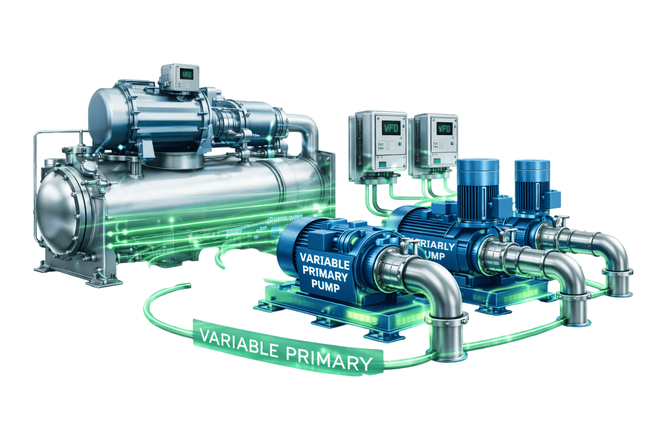
Variable Primary Flow Systems
In variable primary flow systems, PICVs keep coil flows stable while plant flow varies. They reduce the overflow that drives low delta-T, which helps the chillers load properly. The plant still needs a minimum flow bypass to protect the chillers at very low system flow.
Primary–Secondary Variable Flow Systems
With PICVs on the secondary circuit, secondary pumps vary their speed on DP control while terminal flows stay balanced. Lower, well-controlled secondary flow reduces the risk of reverse flow in the decoupler and helps keep supply temperatures stable.
Demand-Based Pump Control Systems
PICVs and demand-based pump control work hand in hand. PICVs keep every coil's flow correct, while demand-based controls reduce pump speed and differential pressure as valves close. Together they deliver the full savings of variable flow.
Multi-Pump Variable Speed Systems
In plants with multiple variable speed pumps, stable PICV-controlled flows make pump staging smoother and more predictable. The pumps respond to real demand rather than to balancing errors.
Pump Control in PICV Based Distribution Systems
Differential Pressure Sensor Location
The DP sensor should sit at or near the index circuit: the PICV and coil that need the most differential pressure at design flow. This is usually the farthest or most demanding terminal. A sensor placed at the pump discharge gives away much of the potential savings.
Reduced DP Setpoint with PICVs
With conventional valves, pumps often run at extra pressure to push enough water to remote zones. With PICVs, the setpoint only needs to cover the index PICV's minimum operating differential pressure plus the coil and branch losses. That usually means a lower and more stable setpoint.
DP Setpoint Reset Using Valve Position
When actuators report their positions to the BMS, the DP setpoint can be lowered until the most-open valve is nearly fully open. It is raised again if any valve saturates. This critical valve reset strategy captures further pumping energy savings.
Sensorless Pump Control with PICVs
Sensorless pumps can work well with PICVs, provided the pump's control curve always supplies at least the minimum pressure the index PICV needs. The curve is set during commissioning and verified at low flow, where the risk of under-supplying remote valves is highest.
Improving Chilled Water Delta-T with PICVs
Preventing Overflow at Terminal Units
Each PICV is preset to its coil's design flow, so no terminal can take more water than it needs. This holds even during morning pull-down, when every valve opens fully. Overflow, the most common cause of low delta-T at the coils, is designed out.
Reducing Low Delta-T Syndrome
Low delta-T syndrome forces plants to circulate far more water than the load needs. For the same cooling load, a delta-T that falls from 5.5 °C to 3.5 °C demands about 57% more flow. By the affinity laws, delivering that extra flow could in theory take close to four times the pumping power. In practice it usually forces extra pumps and chillers online. PICVs tackle the problem at the coils, where it starts.
Energy Valves for Delta-T Management
Energy valves measure supply and return temperatures at the coil. If delta-T falls below a set limit, typically because the coil is fouled or saturated, the valve limits flow to protect the plant's delta-T. Energy valves also log coil energy, which makes them powerful diagnostic tools.
Benefits of PICV Based Distribution
Automatic Dynamic Balancing
Every coil receives its correct flow at every load, with no manual balancing and no drift over time.
Accurate Temperature Control
Full valve authority and stable flows give tighter room and supply air temperature control, with less hunting and fewer comfort complaints.
Reduced Pumping Energy
No overflows, lower DP setpoints and effective setpoint reset let variable speed pumps run slower for more hours.
Improved Chiller Efficiency Through Higher Delta-T
Warmer return water lets chillers load fully and run efficiently. The plant needs fewer chillers and pumps for the same load.
Simplified Commissioning
Commissioning becomes a simple process: preset, verify and record. There is no iterative proportional balancing across the whole building, which saves time and reduces handover risk.
Fewer Valves & Reduced Installation Space
One PICV replaces a control valve, a balancing valve and often a DP regulator. That means fewer joints, less insulation, smaller hook-ups and easier access above ceilings.
Easy System Expansion Without Rebalancing
New floors, tenant fit-outs or additional AHUs can be added without rebalancing the existing system, as long as the pumps can supply the extra flow and pressure.
Want to see how PICVs would perform in your building? Ask Compress India for a hydronic review.
Limitations & Design Challenges
Minimum Operating Differential Pressure (Start-Up Pressure)
A mechanical PICV needs a minimum differential pressure before its regulator starts working, typically around 15–35 kPa depending on make and size. Below this, the valve behaves like a conventional valve and cannot guarantee flow. Pump head and DP setpoints must always provide this minimum at the index valve.
Higher Initial Valve Cost
A PICV costs more than a basic two-way valve. It also replaces a balancing valve and simplifies commissioning, so the difference in installed cost is much smaller. Energy savings often recover what remains.
Sensitivity to Dirt and Water Quality
PICVs have small internal passages and precise regulating parts. Debris, scale or poor water treatment can block them or make them stick. Thorough flushing, strainers and ongoing water treatment are essential.
Incorrect Flow Presetting
A valve preset too low starves its coil, and one preset too high allows overflow. Presetting must follow an accurate schedule and be verified during commissioning.
Actuator Compatibility with Controls
Actuators must match the valve's stroke and force, and the controller's signal type, voltage and control logic. Mismatches cause incomplete strokes, hunting or no control at all.
PICV vs Two-Way Control Valve with Balancing Valve
| Parameter | PICV | Two-Way Control Valve + Balancing Valve |
|---|---|---|
| Components per terminal | One | Two or more |
| Balancing | Dynamic and automatic | Static and manual |
| Flow at part load | Maintained | Drifts with pressure changes |
| Valve authority | Effectively 100% | Varies; often poor at part load |
| Commissioning | Preset and verify | Iterative proportional balancing |
| Delta-T | Protected | Prone to overflow and low delta-T |
| Valve cost | Higher | Lower |
| Installed and lifecycle cost | Often competitive | Higher over time |
PICV vs Three-Way Control Valve
A three-way valve diverts unused chilled water around the coil and back to the return, so system flow stays constant whatever the load. Pumps keep running at full flow and cold water goes back to the chillers, the classic cause of low delta-T. A 2 way pressure independent control valve works the other way: when the coil needs less, the valve closes and system flow falls.
| Parameter | PICV (Two-Way) | Three-Way Control Valve |
|---|---|---|
| System flow | Variable | Constant |
| Pumping energy | Low at part load | High at all loads |
| Return water temperature | Warm, near design | Mixed down by bypassed water |
| Delta-T | Maintained | Low at part load |
| Balancing | Automatic | Manual, including the bypass leg |
| Compatibility with VFD pumps | Excellent | Limited savings |
True 3 way pressure independent control valves are uncommon, and PICV based designs almost always use two-way valves. Sometimes a project needs a three-way function, for example to keep minimum circulation at the end of a long run. The usual solution is either a two-way PICV with a separate small bypass, or a three-way valve combined with an automatic flow limiter.
PICV vs Differential Pressure Control Valve (DPCV)
A differential pressure control valve (DPCV) holds a constant differential pressure across a group of terminals, such as a floor branch or a riser. It works through a capillary connection to a partner valve. Within that group, terminal flows still depend on conventional control and balancing valves. A PICV provides differential pressure control at each individual terminal, combined with flow limitation and modulation.
| Parameter | PICV | DPCV |
|---|---|---|
| Control level | Each terminal unit | A branch, riser or group of terminals |
| Flow limitation at terminals | Built in | Requires separate balancing valves |
| Terminal valve authority | Effectively 100% | Improved, but depends on branch design |
| Typical use | FCUs, AHUs and process coils | Risers, branches and zones with many small terminals |
| Commissioning | Preset and verify each valve | Set the DP, then balance within the branch |
The two also work well together. DPCVs on risers close to the plant can cap differential pressure where it might otherwise exceed the PICVs' maximum rating.
PICV Based Distribution vs Conventional Constant Flow Distribution
| Parameter | PICV Based Distribution | Conventional Constant Flow Distribution |
|---|---|---|
| Terminal valves | Two-way PICVs | Three-way valves or constant flow bypasses |
| System flow | Follows the load | Fixed at design |
| Pump operation | Variable speed on DP control | Constant speed |
| Balancing | Dynamic and automatic | Static and manual |
| Delta-T | Close to design at all loads | Low at part load |
| Chiller loading | Efficient | Extra chillers often running |
| Energy use | Low | High |
| Expansion | Add terminals without rebalancing | Rebalancing required |
ECBC, ASHRAE 90.1 & Green Building Considerations for PICV Systems
Energy codes push chilled water systems towards variable flow, and PICVs are one of the most reliable ways to achieve it in practice. India's Energy Conservation Building Code (ECBC), including its updated versions, and ASHRAE Standard 90.1 both favour hydronic systems with two features:
- two-way valves, so flow varies with load
- pump flow and power that fall significantly at part load, typically through variable speed drives on larger pumps
ASHRAE 90.1 goes further. It calls for differential pressure to be measured near the most remote or most demanding coil and, where DDC controls exist, for the DP setpoint to be reset based on valve positions.
PICVs make these requirements easier to meet, because stable, balanced flows let pumps run at low setpoints without starving remote zones. PICV systems also support energy performance, commissioning and metering goals under green building rating systems such as IGBC, GRIHA and LEED. Compress India works with your MEP consultant to align valve selection, pump controls and documentation with the requirements that apply to your project.
PICV Based Distribution for HVAC
For commercial HVAC, PICV based distribution is now the benchmark for new chilled water systems and the most effective upgrade for existing ones. Compress India delivers each PICV for commercial HVAC system projects as an end-to-end package. Typical projects are office towers, malls, hospitals, hotels and campuses, from FCU valves on every floor to large AHU valves in plant rooms.
Our scope covers PICV valve selection and supply, actuators, coil connection packages, installation, flushing, commissioning and BMS integration. We back it with pump control strategies that turn balanced flow into measurable energy savings, supporting HVAC flow optimization across the whole building.
PICV Based Distribution for Industrial & Process Cooling
Industrial cooling systems face a different challenge: many process users with very different demands sharing one loop. Without pressure independent control, one large user opening up can starve smaller users elsewhere on the line.
PICVs give every process heat exchanger, jacketed vessel and machine cooling circuit a guaranteed, independent flow. Compress India designs PICV based process cooling distribution with robust strainers, water treatment, suitable pressure ratings and process-PLC integration. Production stays stable while pumping energy falls.
Applications of PICV Based Distribution Systems
Commercial Buildings & Office Complexes
Office floors with hundreds of FCUs and several AHUs are ideal for PICVs. Every zone receives its design flow and tenant fit-outs don't upset the balance. The chilled water plant benefits from consistently higher delta-T.
Shopping Malls
Malls combine large common-area AHUs with tenant units that change regularly. PICVs keep anchor stores, food courts and small retail units correctly supplied, even as the tenant mix evolves.
Hospitals
Operating theatres, ICUs, isolation rooms and wards need reliable, precise cooling. PICVs deliver stable flows to critical AHUs and FCUs, while smart actuators give the BMS early warning of control problems.
Data Centers
On CRAH coils and in-row coolers, PICVs keep flow matched to IT load and protect delta-T. New cooling units can be added as white space is built out without disturbing existing ones.
Pharmaceutical Facilities
Cleanroom AHUs demand tight temperature and humidity control. PICVs with high-resolution actuators provide stable coil control, and their predictable, documented flows support validation.
Manufacturing Plants
In many plants, process coolers, machine cooling and production AHUs share one loop. PICVs guarantee each user its flow and stop high-demand equipment from starving the rest.
Hotels
Guest room FCUs, banquet halls and restaurants all run at different times. PICVs keep every room comfortable at any occupancy and reduce the noise that high-pressure valves create.
Airports & Metro Systems
Large terminals and stations have long pipe runs and widely varying loads. PICVs overcome the pressure differences across these networks and keep remote zones supplied during peak passenger periods.
IT Parks & Campuses
Campuses grow building by building. With PICVs, new buildings and floors can be connected to the central plant without rebalancing the existing network.
District Cooling Plants
In district cooling, delta-T directly drives operating cost. PICVs and energy valves at customer connections and energy transfer stations help keep return temperatures high and network flows efficient.
System Design & Sizing
Good PICV system design starts with accurate terminal data and ends with a pump that delivers just enough pressure to the index valve.
Terminal Unit Flow Calculation
Each terminal's design flow comes from its cooling capacity and design delta-T:
Flow (L/s) = Load (kW) ÷ (4.19 × ΔT in °C)
At a 5.5 °C delta-T, a 1 TR fan coil needs roughly 550 L/h and a 30 TR AHU needs about 16.5 m³/h. These flows drive every decision that follows.
PICV Selection Based on Design Flow
PICV sizing is based on design flow, not pipe size. We choose the valve whose flow range covers the design flow with the preset in its recommended band. This avoids undersized valves and very low presets that reduce control resolution.
Minimum Differential Pressure Requirement
Every PICV has a minimum operating differential pressure. The design must give the index valve at least this pressure, plus coil and hook-up losses. That must hold at design flow and across the pump's whole control range.
Pump Head Calculation with PICVs
Pump head is the sum of three parts:
- plant losses through the chiller evaporator, strainers and valves
- supply and return pipe friction to the index terminal
- the index terminal's own requirement: PICV minimum differential pressure, coil pressure drop and hook-up losses
A sensible margin is added, but safety factors are not stacked.
Direct Return vs Reverse Return Piping with PICVs
Reverse return piping was traditionally used to equalize pressure drops between terminals. Because PICVs do the balancing, direct return piping works well and saves pipe, space and cost. The design must still confirm that valves near the pumps won't see more differential pressure than their maximum rating.
Pipe Sizing for Variable Flow Distribution
Pipes are sized for design flow at moderate friction rates and velocities, balancing pump head against pipe cost. Velocities fall at part load, so effective air and dirt separation is essential to keep the system clean and air-free.
PICV Selection Criteria
Flow Range & Valve Size Selection
The valve's flow range must cover the terminal's design flow with room for presetting. Oversized valves lose resolution, and undersized valves cannot pass design flow. PICV valve selection always starts from the flow schedule.
Pressure Rating & Maximum Differential Pressure
The body pressure rating, for example PN16 or PN25, must suit the system's static and pump pressure, which matters in tall buildings. The valve's maximum differential pressure must not be exceeded at any terminal, especially those closest to the pumps.
Actuator Signal & Control Compatibility
The actuator must match the controller's output: on/off, 0–10 V, 2–10 V, 4–20 mA, or BACnet/Modbus. It must also match the supply voltage, feedback requirements and any fail-safe needs.
Body Material & Connection Type
Small PICVs usually have dezincification-resistant brass bodies with threaded ends. Larger valves use cast or ductile iron bodies with flanges. The right choice depends on size, pressure rating, water quality and the project specification.
Flow Measurement Capability
Some PICVs allow flow verification through their test points with a balancing instrument, and electronic PICVs measure flow continuously. If commissioning or M&V needs measured flow, include this capability in the selection.
Common PICV Brands Used in HVAC Projects
Several established manufacturers supply PICVs to Indian HVAC projects. If you are searching for a PICV manufacturer in India, or a pressure independent control valve manufacturer in India, the valve will often come from one of the makes below through their Indian distribution networks. What makes the difference on site is the partner who selects, supplies, installs and commissions it. Compress India works with the make approved by your consultant, or helps you compare options on performance, availability and cost.
Danfoss PICV
Danfoss's AB-QM range is a widely specified PICV family for FCUs and AHUs, available in threaded and flanged sizes. On projects that specify a Danfoss PICV valve, it pairs with Danfoss actuators, including NovoCon digital actuators with BACnet and Modbus connectivity.
Belimo PICV & Energy Valve
The Belimo pressure independent control valve range covers three main products:
- the PICCV valve, a pressure independent characterized control valve built on a characterized ball design
- the Belimo ePIV, an electronic pressure independent valve with an integrated flow sensor
- the Belimo Energy Valve, which adds temperature sensors for delta-T management and energy monitoring
A Belimo PICV is often chosen where compact size or smart valve data is a priority.
IMI Hydronic Engineering PICV
IMI Hydronic Engineering, known for its TA range of balancing products, offers PIBCVs such as TA-Modulator for AHUs and FCUs and TA-Compact-P for small terminal units. Both are supported by IMI's own actuators and balancing instruments.
Siemens PICV
Siemens pressure independent control valves, often called combi valves, belong to the Acvatix range of valves and actuators and come in threaded and flanged versions. When a project specifies a Siemens PICV, we review the Siemens PICV datasheet, as we would for any make. We confirm the flow range, minimum differential pressure and actuator pairing.
Frese PICV
Frese, a Danish manufacturer focused on hydronic balancing, offers compact PICVs for terminal units and larger flanged PICVs for AHUs and plant applications.
Other PICV Brands
Other manufacturers active in the PICV market include Oventrop, Caleffi, FlowCon and Griswold, along with Indian makes. Whatever the brand, we check each valve's flow range, minimum differential pressure, pressure rating and actuator compatibility against your project requirements.
Piping & Installation Arrangement at Terminal Units
Typical PICV Coil Connection Assembly
A typical PICV valve package for an FCU or AHU includes:
- an isolation valve and Y-strainer on the supply side
- the coil connection
- P/T test points, the PICV with actuator, and an isolation valve with union on the return side
FCU packages often add flexible hoses. Supplying the complete package as one kit speeds up installation and keeps quality consistent.
Strainers & Isolation Valves
A strainer upstream of the coil and PICV protects both from debris. Isolation valves on both sides let the strainer, valve or coil be serviced without draining the system.
Flushing Bypass During Installation
A flushing bypass across each coil and valve assembly lets the main pipework be flushed without sending construction debris through coils and PICVs. It is closed once the system is clean.
P/T Test Points & Access for Adjustment
Test points, presetting dials and actuators must stay accessible after ceilings are closed. We coordinate access panels and valve orientation so commissioning and maintenance can be done without dismantling finishes.
Insulation of Valves and Fittings
In a humid climate like Mumbai's, every chilled water valve and fitting must be insulated to prevent condensation. We use removable insulation jackets on valves so the PICV stays accessible, and leave actuators uninsulated and ventilated.
Controls, Automation & BMS Integration
Room / Zone Temperature Control Loop
For FCUs, a room thermostat or controller compares room temperature with setpoint and commands the PICV, either on/off or modulating. Because flow is pressure independent, the loop behaves consistently in every room.
AHU Supply Air Temperature Control
For AHUs, a PID loop modulates the PICV to hold supply air temperature. Full valve authority lets the loop be tuned for fast, stable response without hunting.
Valve Position Feedback to BMS
Position feedback from the actuators tells the BMS how hard each coil is working. It reveals saturated valves, stuck actuators and undersized coils, and it provides the input for critical valve reset.
Critical Valve Reset Logic
The BMS identifies the most-open valves and lowers the pump DP setpoint step by step until one valve is nearly fully open. If a valve saturates, the setpoint is raised again. The logic keeps pump pressure at the minimum the building actually needs.
Smart Actuator Integration (BACnet / Modbus)
Smart actuators bring valve position, flow and alarms directly into the BMS over BACnet or Modbus. Energy valves add temperatures and energy data. We handle addressing, point mapping and graphics so the data is usable from day one.
Energy Efficiency & Power Consumption
PICV energy efficiency comes from two directions: less water pumped around the system, and better chiller operation. Together they make energy efficient chilled water distribution using PICVs one of the most reliable routes to an energy efficient chilled water system.
Pumping Energy Savings with PICVs
With PICVs, pumps no longer push excess pressure to compensate for imbalance. Flows drop as valves close, DP setpoints can be lowered and reset, and VFD pumps run slower for more hours. This is chilled water flow optimization at its most practical. Converting a constant flow system with three-way valves to PICV-based variable flow typically delivers the largest savings.
Chiller Energy Savings from Improved Delta-T
With higher delta-T, each chiller can be fully loaded before the next one starts. Fewer chillers, pumps and cooling tower cells run for the same load, and chillers operate closer to their efficient range.
Measurement & Verification (M&V)
We measure pump power, system flow, supply and return temperatures and delta-T before and after the upgrade, then normalize the results for cooling load. Energy valves and smart actuators can add terminal-level data, showing exactly where performance has improved.
Return on Investment & Payback Analysis
Payback depends on the existing system, operating hours, tariff and scope. Three-way-to-PICV conversions combined with pump VFDs generally pay back fastest. For new projects, reduced commissioning effort and the removal of balancing valves lower the net cost of choosing PICVs. We present a clear payback estimate before you commit.
Installation of PICV Based Distribution Systems
Compress India follows a disciplined PICV installation sequence:
- 1. Submittals and approvals: valve schedules, datasheets, actuator details and connection kit drawings are approved before procurement.
- 2. Pipework and hook-ups: coil connection assemblies are installed with the correct flow direction and orientation, and access is maintained.
- 3. Flushing bypasses: bypasses are fitted so pipework can be cleaned before water passes through coils and PICVs.
- 4. Valve protection: PICV internals are protected, or valves are fitted after flushing, according to manufacturer guidance.
- 5. Actuator mounting and wiring: power, control and feedback wiring is terminated and labelled.
- 6. Insulation: valves and fittings are insulated with removable jackets after pressure testing.
- 7. BMS connection: points are mapped, addressed and tested from the controller.
Flushing, Testing & Commissioning
System Flushing & Cleaning
The system is flushed through the bypasses, chemically cleaned where required and treated, following established pre-commission cleaning practice such as BSRIA BG29. Strainers are cleaned repeatedly until the water runs clear. Only then are coils and PICVs brought into the circuit.
Flow Presetting at Each PICV
Each PICV is preset to its scheduled design flow, and the setting is recorded valve by valve. Settings are checked against the terminal schedule to catch errors before the system goes live.
Differential Pressure Verification Across PICVs
Using the test points, we confirm that the valves, particularly at the index circuit, receive at least their minimum operating differential pressure at design conditions.
Flow Verification Using P/T Points
On valves designed for it, we verify flow through the test points with a balancing instrument. On other valves, we confirm flows at representative terminals by one of three methods:
- coil pressure drop checked against manufacturer data
- clamp-on ultrasonic meters
- system-level flow meters
Actuator Stroke & Control Signal Testing
Each actuator is stroked from fully closed to fully open. We verify the control signal, feedback signal and fail-safe action against the BMS, and configure any stroke limits or characteristic settings at this stage.
Pump DP Setpoint Optimization
Finally, we lower the pump DP setpoint to the minimum that still gives the index PICV its required pressure, and set the reset limits. The final settings are documented in the commissioning report.
Maintenance & AMC for PICV Based Distribution Systems
PICVs themselves need little attention, but the system around them does. Compress India's AMC for PICV systems typically includes:
- Strainer inspection and cleaning at AHUs, FCUs and plant level
- Water quality monitoring and coordination with water treatment
- Actuator checks for stroke, response, feedback and fail-safe operation
- Differential pressure checks at index valves
- Flow verification at sample terminals
- BMS trend reviews of valve positions, delta-T and pump setpoints
- Presetting reviews when terminal loads change
- Insulation and condensation inspections around valves
AMC plans can be comprehensive or non-comprehensive to suit your facility.
Common Problems & Troubleshooting
Insufficient Flow at Terminal Units
Usual causes include:
- blocked strainers
- an incorrect preset
- the valve operating below its minimum differential pressure
- air in the coil
- a closed isolation valve
- an actuator that doesn't open fully
We check each one in turn, from strainer to actuator.
PICV Operating Below Minimum Differential Pressure
Remote valves lose pressure independence when the DP setpoint is too low, the sensor is in the wrong place or piping losses exceed design. Relocating the sensor, raising the setpoint or removing restrictions restores control.
Valve Clogging Due to Dirt & Debris
Construction debris, scale or corrosion products can block PICV internals. Prevention through flushing, strainers and water treatment is best. Clogged valves are cleaned or replaced, and the source of the debris is addressed.
Actuator Failure or Incorrect Control Signal
Symptoms include valves stuck open or closed, or valves that don't respond at all. Causes include power loss, wiring faults, the wrong signal type, reversed action or incorrect addressing on networked actuators. Signal checks and actuator diagnostics identify the fault quickly.
Temperature Hunting at Terminal Units
Hunting usually comes from aggressive control tuning, oversized coils, the wrong valve characteristic or an unstable supply water temperature. Retuning, correct presetting and the right characteristic settings stabilize it.
Low Delta-T Despite PICVs
PICVs prevent overflow, but they cannot fix everything. Delta-T can still be pulled down by:
- fouled coils
- unrealistic setpoints
- presets above design
- remaining three-way valves
- open bypasses
A system-wide review, ideally with energy valve or BMS data, finds the cause.
Retrofitting Existing Systems with PICVs
Many buildings still run three-way valves, or two-way valves with manual balancing. Retrofitting PICVs is one of the most effective ways to improve comfort and cut energy without replacing the chiller plant.
Replacing Three-Way Valves with PICVs
Each three-way valve is replaced with a PICV, and its bypass leg is removed or permanently closed. The system becomes variable flow, so pump and chiller minimum flows must be protected at the plant.
Replacing Two-Way Valves & Balancing Valves with PICVs
Replacing each control valve and balancing valve pair with a single PICV restores automatic balancing and full valve authority, often within the same hook-up space.
Converting Constant Flow Systems to Variable Flow
Beyond the valves, conversion requires plant changes: variable speed pumps, a DP control strategy, and a minimum flow bypass or variable primary controls to protect the chillers. We design the whole conversion, not just the valve swap.
Adding VFDs & DP Control After PICV Retrofit
Once PICVs are in place, adding VFDs to the pumps and a remote DP sensor unlocks most of the pumping savings. Without them, PICVs balance the system but the pumps keep running at full speed.
Phased Retrofit in Occupied Buildings
We retrofit floor by floor or zone by zone, working nights and weekends where needed. Each section is isolated, drained, fitted, flushed and returned to service, so the building stays operational throughout.
Still running three-way valves? Ask Compress India for a PICV retrofit assessment.
PICV Based Distribution System Cost in India
The cost of a PICV based distribution system depends on the number and size of terminal units, the valve and actuator types, and the scope of plant and controls work. A hotel with a few hundred FCU valves is a very different project from a hospital with large AHU valves, energy valves and full BMS integration.
Compress India provides itemized proposals that separate valve supply, installation, commissioning and controls, so you can see exactly where your budget goes.
PICV Price Factors
PICV valve price in India varies with:
- Valve size and flow range, from small FCU valves to large flanged AHU valves
- Valve type: mechanical PICV, electronic PICV or energy valve
- Actuator type: on/off, modulating, smart networked or fail-safe
- Make and country of origin
- Body material, pressure rating and connection type
- Accessories and the contents of the PICV valve package
- Quantity, delivery timelines and stock availability
Factors Affecting Total Project Cost
- Number of terminal units and valve packages
- New installation versus retrofit of existing valves
- Flushing bypasses, system cleaning and water treatment
- Pump VFDs, DP sensors and plant modifications
- BMS integration and smart actuator networking
- Insulation, access panels and ceiling works
- Phased work, night shifts and occupied-building constraints
- Commissioning, M&V and AMC scope
Information Required for a Quotation
To prepare an accurate proposal, please share:
- Terminal unit schedule: AHUs, FCUs and other coils, with capacity, design flow, delta-T and coil pressure drop
- Pipe sizes at each terminal connection
- Chilled water schematic, riser diagram or floor piping layouts
- Pump details and the current pump control method
- System operating pressure or building height, for pressure rating
- Actuator requirements: on/off, modulating, BACnet/Modbus or fail-safe
- Approved or preferred makes
- Existing BMS make and protocols
- For retrofits: current valve types, access constraints and photographs
- Water treatment status and any known dirt or corrosion issues
- Project timeline and working-hour restrictions
Missing some of this? Our engineers can collect it during a site survey.
PICV Supplier & Installation Contractor in Mumbai
Looking for a PICV supplier and installation contractor in Mumbai? Compress India combines valve supply with hydronic engineering and site execution. The right valve is selected, supplied, installed and commissioned by one accountable team.
Mumbai buildings bring their own challenges, and we plan valve selection, access and installation around each of them:
- tall towers with high static pressures
- humid air that demands careful valve insulation
- congested ceiling voids with limited access
- strict working-hour limits in occupied buildings
We work on projects across Mumbai, from Nariman Point, Worli and Prabhadevi to BKC, Kurla, Andheri, Powai, Malad and Borivali.
Book a site survey with Compress India for PICV selection, supply and installation.
PICV Solutions in Mumbai, Navi Mumbai, Thane & Maharashtra
Compress India supports PICV projects across Mumbai and Navi Mumbai (Vashi, Nerul, Belapur, Ghansoli, Airoli, Kharghar and Panvel). In Thane, we cover Wagle Estate, Pokhran Road, Kolshet and Ghodbunder Road. Elsewhere in Maharashtra, we work in Pune, Nashik, Nagpur and Chhatrapati Sambhajinagar. Our solutions include:
- Commercial towers and IT parks: PICV based chilled water distribution for FCUs and AHUs
- Hospitals and healthcare: PICVs with smart actuators for critical areas
- Hotels and residential projects: compact FCU valves with on/off or modulating actuators
- Industrial and pharma plants: PICVs for process heat exchangers, cleanroom AHUs and process cooling
- Retrofits: replacement of three-way and two-way valves with phased execution
- Supply packages: PICVs, actuators and complete coil connection kits
PICV Based Distribution Solutions Across India
As a PICV supplier in India with engineering and execution capability, Compress India also takes up projects beyond Maharashtra, including Delhi NCR, Bengaluru, Hyderabad, Chennai, Ahmedabad, Kolkata, Jaipur and Indore. Our pressure independent control valve supply packages come with valve schedules, presetting data and commissioning guidance, so site teams have everything they need.
Every project follows the same design standards, selection checks and commissioning procedures, wherever it is located. For multi-site organizations, smart actuators and energy valves give central teams consistent data from every building.
Why Choose Compress India for PICV Based Distribution Systems?
Hydronic Design & Balancing Expertise
We understand hydronic balancing from the coil back to the plant. Every PICV is sized from real flows, and every index circuit is checked for pressure.
PICV Selection & Supply Coordination
From flow ranges and presets to actuators and connection kits, we select and supply complete packages. Submittals, datasheets and deliveries are coordinated for you.
Complete Chiller Plant & Pump Integration
PICVs only deliver their full value with the right pump control. We integrate valves, VFD pumps, DP sensors and chiller sequencing into one working system.
Controls & BMS Integration
We connect actuators, feedback signals and smart valves to your BMS, and set up critical valve reset so the data turns into savings.
Installation, Flushing & Commissioning
Our team installs hook-ups, flushes the system properly, presets every valve and verifies pressures and flows before handover.
Retrofit & Energy Optimization
We convert three-way and conventional systems to PICV based variable flow in phases, then measure the results.
AMC & Lifecycle Support
Strainer care, actuator checks, trend reviews and presetting updates keep your system balanced and efficient for its whole life.
How to Select the Right PICV Based Distribution Design
Use these guidelines as a starting point:
- FCU-heavy buildings (offices, hotels): compact threaded PICVs with on/off or modulating actuators
- AHU-heavy plants: larger PICVs with modulating or smart actuators, and energy valves on the largest or most critical coils
- Buildings with a capable BMS: smart actuators and critical valve reset for maximum pump savings
- Tall buildings or large networks: check static pressure ratings and maximum differential pressure, and add riser DPCVs where needed
- Critical facilities: smart actuators with diagnostics and fail-safe functions where required
- Existing three-way valve systems: PICV retrofit with VFDs, DP control and chiller minimum flow protection
- Older or dirty systems: flushing, filtration and water treatment before any valve change
- Tight budgets: mechanical PICVs throughout, with energy valves only at key AHUs
Choosing a PICV for variable flow chilled water system design is easier with a site review. Our engineers can recommend the right valves, actuators and pump controls for your building.
Get a PICV Based Distribution Solution from Compress India
Balanced flows, stable temperatures and lower energy bills all start at the valves. Compress India designs, supplies, installs and supports PICV based distribution systems with one accountable team.
Connect with Our HVAC Execution Team
Call our team or send an enquiry through this page with your terminal unit schedule and drawings. Our engineers will review your system and recommend a site survey where needed. We will then prepare a clear proposal covering valve selection, installation, commissioning and expected savings.
Related Systems Types & Components
Explore our comprehensive range of hydronic system configurations and components designed for efficient water distribution.
Variable Primary Flow Systems
Learn More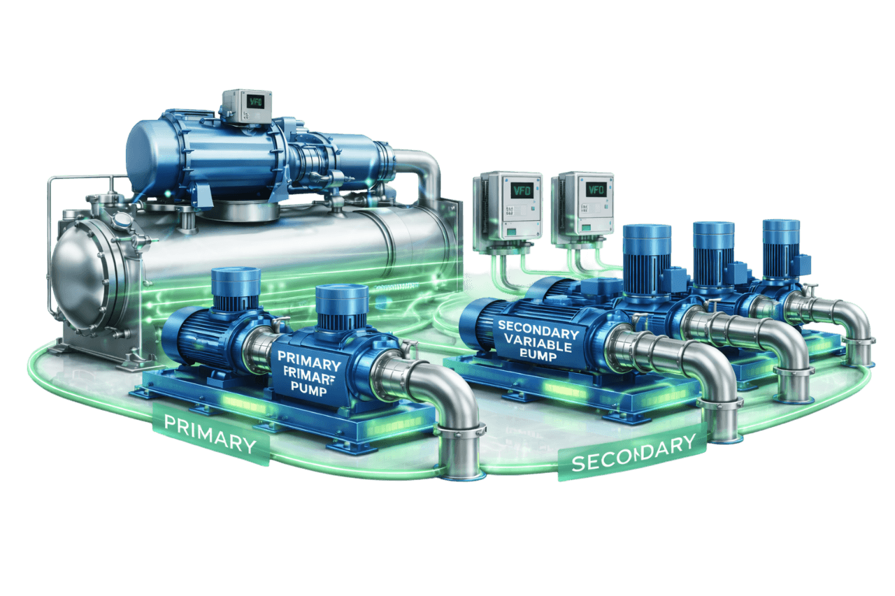
Primary–Secondary Variable Flow Systems
Learn More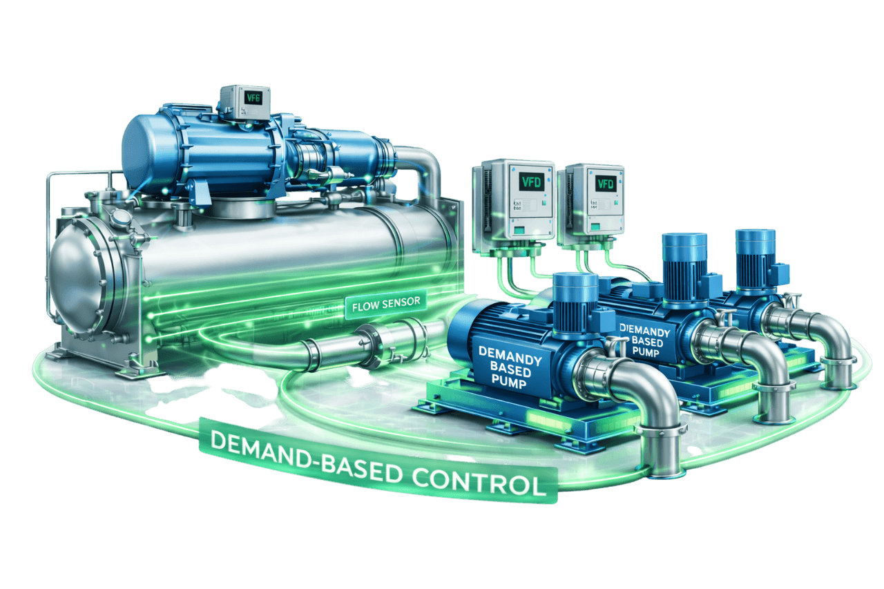
Demand-Based Pump Control Systems
Learn More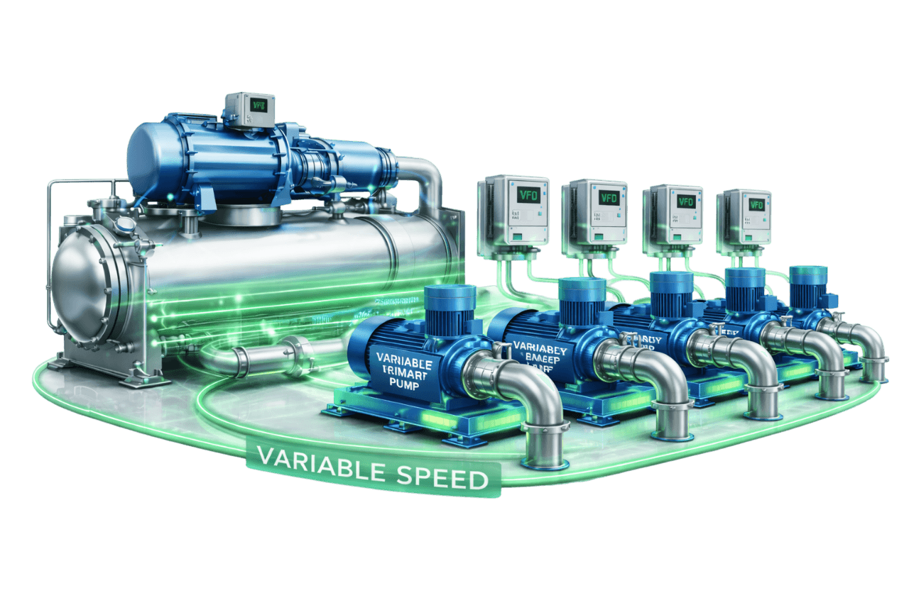
Multi-Pump Variable Speed Configurations
Learn MoreFrequently Asked Questions
Q1. What is a pressure independent control valve (PICV)?
A PICV is a two-way valve that combines a differential pressure regulator, a maximum flow limiter and a modulating control valve. It delivers the required flow to a coil regardless of pressure changes in the rest of the system.
Q2. How does a PICV work?
A diaphragm and spring regulator keeps a constant pressure across the valve's control section. The maximum flow is preset to the coil's design flow, and the actuator modulates the valve between closed and that maximum according to the control signal.
Q3. What is PICV based distribution in HVAC systems?
It is a chilled water or hot water distribution approach in which every terminal unit has its own PICV. The valves balance the system automatically at all loads, while variable speed pumps supply just enough pressure.
Q4. What is the difference between a PICV and a normal two-way control valve?
A normal two-way valve is pressure dependent. Its flow changes when system pressure changes, and it needs a separate balancing valve. A PICV keeps flow stable despite pressure changes, limits maximum flow and has full valve authority, all in one body.
Q5. Do PICVs eliminate the need for balancing valves?
At terminal units, yes, because the PICV performs the balancing function. Depending on the design, some systems still use balancing valves or DPCVs at plant level, on high-pressure risers or for flow measurement.
Q6. What is the difference between static and dynamic balancing?
Static balancing sets flows manually with balancing valves and is accurate only at design load. Dynamic balancing, provided by PICVs, adjusts automatically and keeps flows correct at every load.
Q7. What is the minimum differential pressure required for a PICV to work?
It depends on the make and size. For mechanical PICVs it is typically around 15–35 kPa. The pump and DP setpoint must deliver at least this pressure at the index valve, plus coil and hook-up losses.
Q8. How is a PICV selected and sized?
By design flow, not pipe size. The valve's flow range must cover the terminal's design flow, with the preset in its recommended band. Pressure rating, maximum differential pressure, actuator compatibility and connection type are then checked.
Q9. What is the difference between a PICV and a DPCV?
A PICV controls flow at an individual terminal unit. A DPCV holds a constant differential pressure across a branch or riser, while the terminals within it still need their own control and balancing valves.
Q10. What is an electronic PICV or energy valve?
An electronic PICV measures flow with an integrated sensor and controls it in a closed loop. An energy valve adds supply and return temperature sensors to measure coil energy and manage delta-T, and reports all the data to the BMS.
Q11. Can PICVs be used on AHUs and FCUs?
Yes. Compact threaded PICVs suit FCUs, and larger threaded or flanged PICVs suit AHUs. Both can be paired with on/off, modulating or smart actuators.
Q12. How do PICVs improve chilled water delta-T?
By preventing overflow. Each PICV limits its coil to design flow, so no coil passes excess water that returns too cold. Stable control also avoids the swings that pull delta-T down.
Q13. How do PICVs reduce pumping energy?
PICVs eliminate overflows, allow lower and more stable DP setpoints, and make valve-position-based setpoint reset practical. With VFD pumps, this means lower speeds and lower power for most operating hours.
Q14. Where should the DP sensor be installed in a PICV system?
At or near the index circuit: the terminal that needs the most differential pressure at design flow, usually the farthest or most demanding one. It should not be at the pump discharge.
Q15. Is reverse return piping required with PICVs?
No. PICVs balance flows automatically, so direct return piping works well and saves cost. Valves close to the pumps must still be checked against their maximum differential pressure rating.
Q16. How are PICVs commissioned?
Commissioning follows these steps:
- flush and clean the system
- preset each PICV to its design flow
- verify differential pressure at the index valves
- check flows at representative terminals
- stroke-test the actuators
- optimize the pump DP setpoint
Q17. Can three-way valves be replaced with PICVs in an existing system?
Yes. Each three-way valve is replaced with a PICV and its bypass leg removed or closed. The plant must then be adapted for variable flow, with VFDs, DP control and chiller minimum flow protection.
Q18. What are common problems with PICVs?
The most common are:
- insufficient differential pressure at remote valves
- clogging from dirty water
- incorrect presetting
- actuator faults
- control hunting
Good design, thorough flushing and proper commissioning prevent most of them.
Q19. What maintenance do PICVs require?
They need regular strainer cleaning, good water treatment, periodic actuator checks, DP checks at index valves and BMS trend reviews. PICVs have few wearing parts, but they depend on clean water.
Q20. What is the price of a PICV in India?
PICV price depends on size, flow range, type (mechanical or electronic), actuator, make and quantity. A small FCU valve with an on/off actuator costs far less than a large flanged AHU valve or an energy valve. Compress India provides project-specific quotations based on your valve schedule.
Q21. What information is needed for a PICV based distribution quotation?
We need:
- the terminal unit schedule with flows and coil pressure drops
- pipe sizes and the chilled water schematic
- pump details and system pressure
- actuator and BMS requirements
- approved makes
- for retrofits, existing valve details and site photographs
Q22. Does Compress India supply and install PICV based distribution systems?
Yes. Compress India provides complete PICV based distribution solutions across Mumbai, Maharashtra and India. Our scope covers:
- hydronic design
- PICV selection and supply, with coil connection packages
- installation, flushing and commissioning
- pump control and BMS integration
- retrofits and AMC