Multi-Pump Variable Speed Configurations
(Design, Installation, Commissioning, Retrofit & Lifecycle Support for HVAC Pumping Systems)
Multi-Pump Variable Speed Configurations – HVAC Plant Engineering & Execution
Most chiller plants don't run on a single pump. They run multiple pumps in parallel, two, three or more working together. How those pumps share the load decides how much energy the plant uses, how reliably it runs and how easily it can be maintained. A well-engineered multi-pump variable speed configuration runs the right number of pumps, at the right speed, at every hour of the day.
Compress India designs, installs and commissions multi-pump variable speed systems for chilled water, condenser water, hot water, process cooling and water boosting. Each system combines parallel pumps with VFD control, a proven multi pump controller and carefully engineered pump staging and destaging logic. The result is a pumping plant that stays efficient from light night-time loads to peak afternoon demand.
What we deliver:
- Multi-pump variable speed configuration design for new HVAC and process plants
- Parallel pump selection, header design and plant room layout
- One-VFD-per-pump, common VFD and integrated pump-VFD solutions
- Multi pump VFD control with staging, pump sequencing, speed matching and duty rotation
- Retrofits, commissioning, BMS integration and AMC support
Send us your pump schedule and plant layout, and our engineers will review your multi-pump configuration.
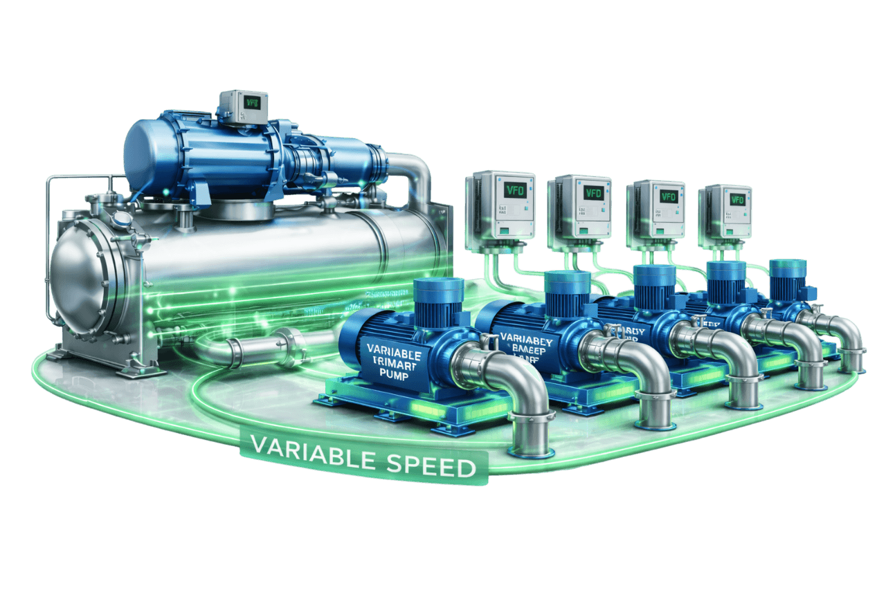
Putting several pumps side by side on a common header is easy. Making them work as one efficient, stable system is not. Parallel pumps can fight each other, hunt between stages, run far from their best efficiency point or deadhead when their speeds drift apart. Each of these problems is either designed out or designed in long before the plant starts.
Compress India handles multi-pump systems as complete engineering and execution projects:
- 1. Load profile analysis: we study how your flow demand varies across the day, the week and the year.
- 2. Hydraulic design: we develop the system curve, the combined parallel pump curves and the operating point at every stage.
- 3. Configuration selection: we fix the number of pumps, their size, and whether they are headered or dedicated.
- 4. Equipment selection: we select pumps, VFDs, valves, sensors and the multi pump controller.
- 5. Execution: we install the piping, electrical work, panels and controls, with planned shutdowns.
- 6. Commissioning: we set up the VFDs, test staging, tune control loops and verify flow and pressure.
- 7. Lifecycle support: we provide performance reviews, AMC and upgrades as your plant evolves.
You get one accountable team for hydraulics, electrical work and controls, which is exactly what multi-pump systems need.
What Is a Multi-Pump Variable Speed Configuration?
A multi-pump variable speed configuration is a pumping arrangement in which two or more pumps fitted with variable frequency drives share a common duty. Most often they are connected in parallel on common suction and discharge headers. A controller decides how many pumps run and at what speed, so the combined output always matches the system's flow and pressure requirement.
When demand is low, a single lead pump runs at reduced speed. As demand rises, it speeds up. When it can no longer keep up efficiently, the controller brings in a second pump, and both run at a matched, lower speed. The reverse happens as demand falls.
This approach is also called multi pump VFD control or variable speed parallel pump operation. It is used for chilled water pumps in parallel, condenser water pump sets, heating systems, process cooling and variable speed booster pump systems in high-rise buildings.
Why Use Multiple Variable Speed Pumps Instead of One Large Pump?
A single large pump can handle design flow, but real plants spend most of their hours well below design. Here is why pumps are connected in parallel instead of relying on one large pump:
- Wider turndown: each smaller pump has a lower minimum flow, so the system can serve very light loads without bypassing water or dropping below safe operating limits.
- Better low-load efficiency: at low demand, one small pump running close to its best efficiency point typically draws less power than a large pump running far to the left of its BEP.
- Built-in redundancy: if one pump or drive fails, the others keep the plant running. With three 50% pumps, the standby unit is only half the size of the standby a single-pump design needs.
- Maintenance without shutdown: one pump can be isolated and serviced while the rest carry the load.
- Easier handling: smaller pumps and motors are simpler to move, install and replace in compact plant rooms.
- Room to grow: capacity can be added later with another pump on the header.
The advantages of parallel pumps are strongest in plants with long hours at part load. Typical examples are offices at night, hospitals in the cooler months, and data centers during partial IT build-out. Compress India models your load profile before recommending a configuration, so the choice fits your plant rather than a rule of thumb.
How a Multi-Pump Variable Speed System Works
Here is how a well-controlled multi-pump system moves through the day, from light load to peak and back again.
1. Lead Pump Operation at Low Demand
At light load, only the lead pump runs. Its VFD holds the control setpoint by running at reduced speed. That setpoint is usually differential pressure at the index circuit, or discharge pressure in booster systems. The remaining pumps stay on standby, ready to start.
2. Speed Increase as Demand Rises
As control valves open and demand grows, the controller raises the lead pump's speed to hold setpoint. Flow rises in step with speed, and the pump moves along the system curve towards its design point.
3. Staging Additional Pumps On
Deciding when to stage on the second pump is central to efficient operation. The trigger is typically one of two conditions. The first is when the lead pump runs above a high-speed threshold, often around 90–95%, for a set time and still cannot hold setpoint. The second is when measured flow shows that two pumps would run more efficiently than one. The incoming pump ramps up while the lead pump eases back, so system pressure stays stable during the transition.
4. Equal Speed Operation of Running Pumps
Once two or more identical pumps are running, the controller sends the same speed command to all of them. This parallel pump speed matching makes each pump share the flow equally and operate at the same point on its curve. It also prevents one pump from being overpowered by the others.
5. Staging Pumps Off as Demand Falls
As demand drops, the running pumps slow down together. When the remaining pumps can comfortably carry the load, one pump ramps down and stops while the others speed up to take over its share. Deadbands and time delays make this happen once, cleanly, rather than repeatedly.
Main Components of a Multi-Pump Variable Speed System
| Component | Function in the System |
|---|---|
| Duty and standby pumps | Identical or matched pumps sized for the required flow split |
| VFD for each pump | Controls speed and provides soft start and pump protection |
| Multi pump controller / PLC | Runs staging, sequencing, speed matching and alternation logic |
| Differential pressure or pressure transmitters | Provide the control signal for pump speed |
| Flow meter | Supports flow-based staging, minimum flow protection and M&V |
| Suction and discharge headers | Distribute flow evenly to and from each pump |
| Non-slam check valves | Prevent reverse flow through idle pumps |
| Isolation valves | Allow each pump to be serviced without draining the system |
| Strainers / suction diffusers | Protect impellers and condition inlet flow |
| Flexible connectors and vibration isolators | Reduce noise and stress on piping and structure |
| VFD bypass starters | Keep a pump running if its drive fails, where specified |
| Harmonic mitigation | Controls distortion from the drive group |
| Energy meters | Measure pump kW and kWh for performance tracking |
| BMS / chiller plant manager interface | Supervisory control, alarms and trending |
| Pressure tank (booster sets) | Stabilizes pressure and supports low-flow shutdown |
Parallel Pump Operation Fundamentals
What happens when pumps run in parallel? Understanding the hydraulics is the key to designing a system that behaves the way you expect.
Combined Pump Curves in Parallel Operation
In parallel operation, pumps share the same head and their flows add. The parallel pump curve is built by adding the flow of each running pump at the same head. Two identical pumps produce a combined curve with the same shut-off head as one pump, but twice the flow at any given head.
System Curve & Operating Point
The operating point is where the combined pump curve crosses the parallel pump system curve. System resistance rises with flow, so adding a second identical pump does not double the flow. In a typical friction-dominated HVAC loop, the second pump often adds only 20–50% more flow. The reverse also matters: when one pump stops, the remaining pump runs out to the right on its curve. It then draws more power and needs more NPSH, and the design must allow for both.
Pump Affinity Laws in Multi-Pump Systems
The affinity laws apply to every pump in the set: flow varies with speed, head with speed squared and power with speed cubed. They also explain why staging matters. For the same total flow and head, running more pumps at lower speed moves each pump left on its curve. Running fewer pumps at higher speed moves each pump right. The most efficient combination is the one that keeps each pump closest to its best efficiency point.
Wire-to-Water Efficiency
Pump efficiency alone doesn't tell the whole story. Wire-to-water efficiency is the hydraulic power delivered to the water divided by the electrical power drawn from the supply. It combines pump, motor and VFD efficiency. In multi-pump systems it is the right yardstick for staging decisions, because a lightly loaded motor and drive can waste as much energy as a pump running away from its BEP.
Types of Multi-Pump Variable Speed Configurations
All Pumps with Individual VFDs
Every pump has its own drive. This is the most flexible and efficient arrangement: pumps can be speed-matched, staged smoothly and started softly, and a drive failure affects only one pump. For most HVAC plants, one VFD per pump is the configuration we recommend.
One VFD Pump with Constant Speed Assist Pumps
One pump runs on a VFD, and the others start across the line at fixed speed when more flow is needed. Capital cost is lower, but control is compromised. A fixed-speed pump always runs flat out, and when the VFD pump slows down beside it, the VFD pump can be pushed towards shut-off and deadheaded. The controller must therefore keep the VFD pump above a safe minimum speed whenever an assist pump is running.
Common VFD Serving Multiple Pumps
One drive can feed several identical motors at once, each with its own overload protection, or switch between pumps through contactors. This saves on drive cost and guarantees equal speed. However, the whole set now depends on one drive. A pump also cannot be connected to a running drive without ramping down first, which complicates staging. We generally reserve this approach for small, non-critical systems.
Integrated Pump–VFD Units
Each pump comes with a motor-mounted drive, factory-matched and pre-programmed. Many integrated units include built-in multi-pump functions. These let two or more pumps share staging, alternation and speed matching over a communication link, reducing the need for a separate controller. They save panel space and simplify retrofits in compact plant rooms.
Packaged Multi-Pump Booster Sets
A variable speed booster pump system combines several vertical multistage pumps (commonly two to six) on a single skid. The skid also carries VFDs, a multi pump controller, pressure transmitters, manifolds and a pressure tank. These sets hold constant discharge pressure for domestic water in high-rise buildings, hotels, hospitals and campuses. They stage pumps as tap demand changes and stop at very low flow to save energy.
Comparison Table – Multi-Pump VFD Configurations
This table answers one of the most common design questions: one VFD per pump vs common VFD, and the alternatives in between.
| Configuration | Efficiency | Control Stability | Redundancy | Capital Cost | Best Suited For |
|---|---|---|---|---|---|
| Individual VFD per pump | Highest | Excellent | High | Higher | Most HVAC and process plants |
| One VFD + constant speed assist pumps | Moderate | Fair, with deadheading risk | Moderate | Lower | Budget systems with limited turndown |
| Common VFD for multiple pumps | Good | Good, with equal speed | Low, single drive | Lower | Small, non-critical systems |
| Integrated pump-VFD units | High | Excellent | High | Moderate to higher | Retrofits and compact plant rooms |
| Packaged booster sets | High | Excellent | High | Moderate | Domestic water pressure boosting |
Parallel vs Series Pump Configurations
Pumps in series vs parallel: both arrangements combine pumps, but for opposite purposes.
Parallel Variable Speed Pumps
Parallel pumps add flow at the same head. They suit systems where flow demand varies widely, such as chilled water and heating distribution, and they provide natural redundancy. Almost every HVAC multi-pump plant uses variable speed pumps in parallel.
Series Variable Speed Pumps
Series pumps add head at the same flow, because the discharge of one pump feeds the suction of the next. Series arrangements suit very high head duties, long transfer lines and tall buildings; a multistage pump is effectively several series stages in one casing. Downstream pumps must be rated for the combined pressure. A stopped pump in series also adds resistance unless a bypass is provided.
Comparison Table – Parallel vs Series Pumps
| Parameter | Parallel Pumps | Series Pumps |
|---|---|---|
| What adds up | Flow at the same head | Head at the same flow |
| Main purpose | Meet variable or high flow demand | Meet high head demand |
| Redundancy | High; the remaining pumps keep running | Low; a stopped pump restricts flow unless bypassed |
| Typical HVAC use | Chilled water, condenser water, heating | Zone boosting, high-rise transfer, long lines |
| Pressure rating | Same for all pumps | Downstream pump sees the combined pressure |
| Variable speed control | Common, with staging and speed matching | Less common; needs coordinated speed control |
Equal vs Unequal Pump Sizing
Identical Pumps in Parallel
Identical pumps are the simplest and safest choice. They share flow equally at equal speed, their combined curve is predictable, spare parts are interchangeable and any pump can act as the lead. For most multi-pump variable speed configurations, identical pumps are the starting point.
Unequal Pump Sizes (Large + Small / Jockey Pump)
Pairing large pumps with a small one, often called a pony or jockey pump, can improve efficiency in plants with long periods of very low demand. The small pump handles night-time or weekend loads, and the large pumps take over during the day. The risk comes when unequal pumps run together. The smaller pump usually has a lower shut-off head and can be pushed off its curve. The staging logic must either keep these pumps from running together or keep their speeds in a range where both deliver flow.
Selecting the Right Number of Pumps
How many pumps can run in parallel? In theory, many. In practice, each additional pump adds less flow on a rising system curve, while adding cost, space and control complexity. HVAC plants commonly use two to four duty pumps plus a standby, arranged as 2 × 100%, 3 × 50% or 4 × 33%. The right number depends on the load profile, required turndown, redundancy, plant room space and budget.
Headered vs Dedicated Multi-Pump Arrangements
Headered Variable Speed Pumps
In a headered arrangement, all pumps discharge into a common header that feeds all chillers or loads. Any pump can serve any chiller, and the number of running pumps does not have to match the number of running chillers. This gives excellent redundancy and flexibility. It requires motorized isolation valves on the chillers and good flow control to share flow correctly.
Dedicated Variable Speed Pumps
In a dedicated arrangement, each pump is piped to its own chiller, boiler or load. The pump and its chiller start and stop together, which keeps controls simple and makes each chiller's flow easy to manage. A pump failure, however, takes its chiller out of service unless crossover piping is provided. Each pump must also be matched to its chiller's pressure drop.
Comparison Table – Headered vs Dedicated Pumps
| Parameter | Headered Pumps | Dedicated Pumps |
|---|---|---|
| Pump-to-chiller relationship | Any pump serves any chiller | One pump per chiller |
| Redundancy | High | Lower without crossover piping |
| Staging flexibility | Pumps staged independently of chillers | Pumps staged with chillers |
| Control complexity | Higher | Lower |
| Chiller isolation valves | Required | Not usually required |
| Best suited for | Variable primary flow and larger plants | Smaller plants, unequal chillers, simple sequences |
Pump Staging Strategies for Multi-Pump VFD Systems
Pump staging and destaging logic decides how many pumps run. Pump sequencing decides which ones. When both are right, the plant runs efficiently and quietly. When they are wrong, pumps cycle, hunt and waste energy.
Speed-Based Staging
The controller stages on another pump when the running pumps exceed a high-speed limit for a set period while setpoint is still not met. That limit is commonly around 90–95%. It stages off when speed falls below a calculated lower limit at which the remaining pumps can carry the load without exceeding their own upper limit. Speed-based staging is simple and needs no flow meter, which makes it a common choice.
Flow-Based Staging
With a reliable flow meter, pumps are staged on measured flow. The controller compares total flow with the capacity of the running pumps and adds or removes a pump at set thresholds. This gives precise, predictable staging. It works well in variable primary systems, where flow is already measured to protect the chillers.
Best Efficiency Point (BEP) Based Staging
BEP-based staging keeps each running pump inside a flow band around its best efficiency point. When per-pump flow moves too far right of BEP, another pump comes on. When it falls too far left, one pump goes off. Operating parallel pumps near their best efficiency point is built directly into the staging logic.
Power / Efficiency Optimized Staging
The most advanced approach compares the total input power of running N pumps against N+1 pumps at the current flow and head, then selects whichever uses less energy. It relies on accurate pump curves and power monitoring, and it maximizes parallel pump efficiency across the whole operating range.
Staging Deadband & Time Delays
Stage-on and stage-off points must be separated by a deadband, and each decision needs a time delay. Without them, the system adds a pump, sees pressure rise, removes the pump and repeats the cycle. Minimum run and minimum off times protect motors and drives from frequent starts.
Lead–Lag Rotation & Run-Hour Equalization
Pump sequencing rotates the lead pump on a schedule or by run hours, so wear is spread evenly and standby pumps are exercised regularly. Rotation is best carried out at low load, and a failed pump is automatically skipped in the sequence.
Speed Control Methods for Multi-Pump Systems
Staging decides how many pumps run; speed control decides how fast they run. In most multi-pump systems, one control loop sets a common speed for all running pumps. Booster sets usually hold a constant discharge pressure. HVAC distribution systems use one of the methods below.
Differential Pressure Control
This is the most common method in HVAC. A DP transmitter at the index circuit feeds the controller. The controller adjusts the common pump speed to hold setpoint as control valves open and close.
Differential Pressure Setpoint Reset
Rather than holding a fixed DP setpoint, the controller lowers it when valve positions or load show that zones are satisfied, and raises it when a zone runs short. Lower setpoints reduce the speed of every running pump and increase savings.
Flow-Based Speed Control
Pumps are controlled to deliver a target flow, for example to track chiller flow in variable primary plants or to meet a process demand. This method requires an accurate flow meter and a clear flow setpoint strategy.
Sensorless Speed Control
The drives estimate flow and head from each pump's performance data and electrical readings, then follow a programmed control curve. Sensorless control reduces field instrumentation and pairs well with integrated pump-VFD units. It is especially useful where remote DP sensing is difficult to install.
Multi-Pump Variable Speed Configurations by System Type
Chilled Water Primary Pumps
In variable primary plants, headered primary pumps with individual VFDs serve all chillers. Staging must respect each chiller's minimum flow and its limit on how quickly flow can change. Pump staging is therefore coordinated with chiller staging and the minimum-flow bypass.
Chilled Water Secondary Pumps
Chilled water pumps in parallel on the secondary loop are the classic multi-pump application. Two or three pumps with individual VFDs run on remote DP control, staged by speed or flow. They serve the building from light night loads to peak afternoon demand.
Condenser Water Pumps
Condenser water pumps are often dedicated to individual chillers, or headered together with the cooling towers. They usually run at fixed flows. VFDs are used to trim each pump to the correct flow, or to support optimized condenser flow within chiller and cooling tower minimum limits. Open condenser systems also need careful NPSH checks at the tower basin.
Hot Water / Heating Pumps
Heating systems in hospitals, hotels and industrial plants use parallel pumps with VFDs on DP or proportional pressure control. Multi-pump arrangements handle wide seasonal swings in heating demand while keeping redundancy for critical areas.
Process Cooling Pumps
Process cooling loops need stable header pressure and uninterrupted flow. Multi-pump variable speed sets with an N+1 standby, fast automatic changeover and process-PLC integration keep production running. They also trim energy use during low-output shifts.
Multi-Pump Variable Speed Pumping in Chilled Water Configurations
Variable Primary Flow Systems
A single headered set of variable speed pumps serves both the chillers and the building. Pump staging is independent of chiller staging. Flow must stay above chiller minimums, which flow meters and a bypass valve protect.
Primary–Secondary Variable Flow Systems
Primary pumps, often dedicated to chillers, and secondary pumps, usually headered in parallel, both run on VFDs. Secondary pumps stage on building demand. Primary pumps track secondary flow so the decoupler stays in slight forward flow.
Multi-Chiller Plants
In plants with three, four or more chillers, the pumping configuration must support every chiller combination. We coordinate pump staging with chiller sequencing, isolation valve control and minimum flow logic, so the right pumps serve the right chillers at every load.
Distributed Pumping Systems
In distributed pumping, smaller variable speed pumps at each building or zone draw from a low-pressure main loop. Each zone runs its own duty/standby pair or small pump set, staging and controlling to its own demand.
Redundancy in Multi-Pump Variable Speed Systems
N+1 Standby Pump Integration
N+1 means one more pump than design load requires. In a 3 × 50% arrangement, two pumps meet design flow and the third stands by. The standby pump is fully included in rotation, so it runs regularly and is ready when needed.
VFD Failure & Bypass Strategy
If a drive fails, a bypass starter can run its pump at full speed across the line. Full-speed operation can over-pressurize the system, so bypass mode must be engineered with pressure limits or throttling in mind. In many N+1 systems, the better strategy is to lock out the failed pump and let the healthy VFD pumps carry the load.
Automatic Changeover on Pump or VFD Fault
Changeover is triggered when a pump trips, a drive faults or a flow-proving signal is lost. The controller then removes that pump from service, starts the next available pump and raises an alarm. Changeover happens within seconds, with ramp rates set to avoid pressure surges.
Benefits of Multi-Pump Variable Speed Configurations
High Efficiency Across a Wide Load Range
Staging the right number of pumps keeps each one closer to its best efficiency point, from minimum load to peak demand.
Better Part-Load Performance
At light loads, one smaller pump takes over from a large pump that would otherwise run at low speed far from its BEP. The result is higher wire-to-water efficiency and steadier control when demand is lowest.
Reduced Energy Consumption
Variable speed operation already cuts pump energy sharply compared with constant speed pumping. Correct staging adds further savings at low load and avoids the waste of running more pumps than the load needs.
Built-In Redundancy
With N+1 pumps and individual drives, no single pump or VFD failure stops the plant.
Maintenance Without System Shutdown
Pumps, seals, bearings and drives can be serviced one at a time while the other pumps keep the system running.
Longer Pump & Motor Life
Duty rotation spreads run hours evenly. Reduced-speed operation lowers bearing loads, vibration and seal wear on every pump.
Flexible Capacity Expansion
A headered system designed with space for future pumps can grow with the building. Adding a pump with its own VFD on the header increases capacity without replacing the existing plant.
Want to see what these benefits are worth in your plant? Talk to Compress India about a multi-pump system review.
Limitations & Design Challenges
Pump Hunting & Staging Instability
Poorly set staging thresholds, missing deadbands or aggressive PID tuning make pumps start and stop repeatedly or cause speeds to oscillate.
Pumps Operating Away from BEP
If pumps are oversized or staging ignores efficiency, pumps spend long periods far from BEP. They lose efficiency and suffer more vibration and wear.
Minimum Speed & Minimum Flow Limits
Every pump has a minimum continuous stable flow and a minimum practical speed. Staging and speed limits must keep each running pump above these values, particularly during stage-down and at night.
Flow Imbalance with Unequal Pumps
Unequal pumps, or identical pumps at different speeds, share flow unevenly. The weaker pump can be pushed towards shut-off, where it overheats and suffers damage.
Higher Initial Cost of Multiple VFDs
Several drives, a multi pump controller, extra valves and larger headers cost more upfront than a single pump. The investment is justified by redundancy, turndown and lifecycle savings, and we quantify these before you decide.
Harmonics & Power Quality Considerations
Multiple VFDs on one supply add up to a significant non-linear load. Harmonic mitigation must be planned for the whole drive group rather than drive by drive.
Multi-Pump Variable Speed vs Single Large Variable Speed Pump
| Parameter | Multi-Pump Variable Speed | Single Large Variable Speed Pump |
|---|---|---|
| Turndown | Wide, because small pumps reach lower flows | Limited by the large pump's minimum flow |
| Efficiency at low load | Higher | Lower, as the pump runs far left of BEP |
| Efficiency near design load | Similar | Similar, sometimes slightly better |
| Redundancy | Built in, with a smaller standby pump | Needs a full-size standby pump |
| Maintenance | One pump at a time, no shutdown | Relies on the standby for any maintenance |
| Controls | Staging and speed matching required | Simpler |
| Plant room layout | More pumps with smaller footprints | Fewer, larger pumps |
Multiple pumps are the stronger choice when turndown, redundancy and maintainability matter, or when the plant spends long hours at light load. A single large variable speed pump with a full-size standby can suit plants that run close to design most of the time. Compress India compares both options against your actual load profile before recommending one.
Multi-Pump Variable Speed vs Constant Speed Multi-Pump Systems
| Parameter | Variable Speed Multi-Pump | Constant Speed Multi-Pump |
|---|---|---|
| Flow control | Speed control plus staging | Staging plus throttling or bypass |
| Energy at part load | Low | High |
| Pressure stability | Smooth | Steps as pumps start and stop |
| Starting | Soft start through VFDs | DOL or star-delta inrush and water hammer |
| Parallel operation | Speed-matched, balanced flow | Fixed curves, possible imbalance |
| Monitoring | Speed, power, flow and alarms per pump | Run and trip status only |
| Upfront cost | Higher | Lower |
| Lifecycle cost | Lower | Higher |
Many older plants in India still run constant speed pumps in parallel. It is common to find two pumps left running all day "to be safe", even at light load. Converting such plants to multi-pump variable speed operation is one of the most cost-effective upgrades available in the plant room.
Multi-Pump Variable Speed Configurations for HVAC
For commercial and institutional buildings, Compress India engineers multi-pump variable speed configurations across the complete hydronic system. This covers chilled water primary and secondary pumps, condenser water pumps, heating pumps and domestic water booster sets. Every project comes with documented staging sequences, speed control strategy and fault responses, so operators and BMS teams know exactly how the pump plant behaves.
The same engineering rigour applies whether you are building a new plant, adding chillers to an existing one, or converting fixed-speed parallel pumps to intelligent variable speed operation.
Multi-Pump Variable Speed Configurations for Industrial & Process Cooling
In industry, a pump failure can stop a production line. Our multi-pump solutions for process cooling cover process chilled water, cooling tower circuits, machine and compressor cooling, and utility water. Each is built around N+1 redundancy and fast automatic changeover.
Staging is tuned to production patterns, so the plant follows shift changes, batch cycles and weekend shutdowns without wasting energy. Integration with process PLCs gives production teams direct visibility of pump status, flow and pressure.
Applications of Multi-Pump Variable Speed Configurations
Commercial Buildings & Office Complexes
Office buildings swing from full occupancy to near-empty floors every evening. A 3 × 50% or 4 × 33% parallel set lets one small pump carry the night load efficiently, while two or three pumps cover the working day.
Shopping Malls
Malls run long hours with changing loads from anchor stores, food courts and cinemas. Multi-pump staging follows the load through the day and keeps standby capacity ready for peak weekend crowds.
Hospitals
Hospitals cannot afford a pumping failure. N+1 parallel pumps with individual VFDs, automatic changeover and backup control modes keep operating theatres, ICUs and wards supplied around the clock.
Data Centers
Data centers need concurrently maintainable cooling. Multi-pump configurations with redundant drives, fast fault changeover and staging tuned for steady IT loads protect uptime and control energy use as the facility grows.
Pharmaceutical Facilities
Cleanroom HVAC and process cooling in pharma plants need stable pressure and consistent performance. Speed-matched parallel pumps with documented staging sequences support predictable, auditable operation.
Manufacturing Plants
Production loads rise and fall with shifts, batches and seasons. Multi-pump variable speed sets on process cooling and utility loops follow those changes and keep a standby pump ready for critical lines.
Hotels
Hotels need chilled water and domestic water on demand. Parallel VFD chilled water pumps handle occupancy swings, while a variable speed booster pump system delivers steady water pressure to guest rooms on every floor.
Airports & Metro Systems
Large terminals and underground stations run extensive pumping networks with strict reliability requirements. Headered multi-pump plants with N+1 redundancy keep cooling available through peak passenger periods and maintenance windows.
IT Parks & Campuses
Central plants serving several buildings see loads build up as tenants move in. Headered multi-pump systems allow capacity to be added in stages, so pump investment tracks actual occupancy.
District Cooling Plants
District cooling plants rely on large headered pump banks serving extensive networks. Efficiency-optimized staging, multi-chiller coordination and distributed pumping keep pumping energy under control at every load.
System Design & Sizing
System Curve Development
We build the system curve from the pressure losses along the index circuit, the control head needed at the critical load, and any static head in open systems. This curve is the reference against which every pump combination is evaluated.
Design Flow & Head Calculation
Design flow comes from peak load and design delta-T. Design head comes from friction losses along the index path, through chillers, coils, control valves, strainers and fittings. We avoid stacking safety margins, because inflated heads push parallel pumps away from BEP for most of their operating life.
Number and Size of Pumps Selection
We compare arrangements such as 2 × 100%, 3 × 50% and 4 × 33% against your load profile. Each option is checked for per-pump operating points at every stage, turndown at minimum load, standby capacity and cost. The selected configuration then performs well across all operating hours, not only at design.
Minimum Flow & Minimum Speed Calculation
For each pump, we establish two limits: the minimum continuous stable flow from manufacturer data, and the minimum speed needed to generate the control head at low flow. For chilled water primary pumps, chiller minimum flow is added to the checks. Staging and speed limits are then set so no running pump falls below these values.
Header and Pipe Sizing
Suction and discharge headers are sized for low, even velocities, so every pump receives steady flow and sees the same pressure at its connection. Suction headers are sized more conservatively than discharge headers to guard against turbulence and cavitation. Branch connections are arranged symmetrically wherever possible.
NPSH Calculation
Net positive suction head available (NPSHa) is calculated as the absolute pressure at the liquid surface, plus or minus the static height, minus suction friction losses and the vapour pressure of the liquid, all expressed as head. NPSHa must exceed the pump's required NPSH (NPSHr) with a safety margin. In parallel systems, the check must include runout. When one pump stops, the remaining pump moves right on its curve and its NPSHr rises. This matters most for condenser water pumps drawing from cooling tower basins and for booster pumps drawing from tanks.
Pump & VFD Selection Criteria
End-Suction vs Split-Case Pumps
End-suction pumps are compact and cost-effective for small to medium flows. Horizontal split-case pumps suit larger flows and offer high efficiency. They can be serviced by lifting the top casing without disturbing the piping or motor. We select between them based on flow, efficiency, space and maintenance access.
Inline Pumps
Vertical inline pumps mount directly in the pipework and save floor space, which makes them popular in compact Mumbai plant rooms. They suit small to medium duties and work well as parallel pairs or as sets with integrated drives.
Pump Selection for Variable Speed Operation
For parallel variable speed duty, pumps should have stable, steadily rising curves with matched shut-off heads. Each pump's BEP should sit close to its design operating point, typically slightly to the right. The pump then stays efficient as staging and speed reduction move it left. Motors must be non-overloading at the runout point reached when fewer pumps are running.
VFD Sizing and Selection
Each VFD is sized on motor full-load current, derated for ambient temperature and enclosure conditions, and selected for variable torque duty. For multi-pump systems, we also look for built-in multi-pump or cascade functions and fieldbus communication for speed matching. Using the same drive model across the set simplifies spares.
IE3 / IE4 Motor Selection
High-efficiency IE3 and IE4 motors reduce losses on every running pump. Motors must be inverter-duty rated, keep adequate cooling at reduced speed and include bearing current protection on larger frames.
Harmonic Filters & Line Reactors
Several drives on one supply multiply harmonic currents. Depending on the total drive load, mitigation may include DC chokes or line reactors on each VFD, a shared active harmonic filter at the MCC, or low-harmonic drives. We assess the whole group together, so both compliance and cost are optimized.
Piping Layout & Plant Room Arrangement
Suction & Discharge Header Design
Good multi-pump performance starts with good piping. Headers are arranged so every pump receives uniform flow. We provide straight runs or suction diffusers at pump inlets and install eccentric reducers on suction lines flat side up. We avoid elbows directly at the pump suction, where they would distort the inlet flow.
Isolation Valves, Check Valves & Strainers
Every pump gets isolation valves on suction and discharge, so it can be removed while the others run. A non-slam check valve on each discharge prevents reverse flow through idle pumps. Strainers or suction diffusers protect the impellers.
Flexible Connections & Vibration Isolation
Flexible connectors at the pump nozzles, inertia bases and spring isolators stop vibration and noise from travelling into the piping and structure. This is especially important where plant rooms sit close to occupied spaces.
Pressure Gauges & Sensor Placement
Suction and discharge gauges on every pump make field checks quick and reliable. Control sensors are placed where they genuinely represent the system: DP transmitters at the index circuit for HVAC distribution, and discharge header transmitters for booster sets.
Service Clearances for Pump Removal
We plan clearances for pulling motors and rotating assemblies, operating valves and reaching drives. We also plan lifting points or beams for heavy components. Good clearance design keeps maintenance quick and safe for decades.
Electrical & VFD Panel Arrangement
Individual VFD Panels vs MCC Integration
Drives can be mounted in individual panels near each pump or grouped in a motor control centre (MCC) with the multi pump controller. MCC integration centralizes cooling, cabling and harmonic mitigation. Individual panels simplify retrofits and limit the impact of a single panel fault.
VFD Bypass Starters
Where the design calls for it, each VFD is paired with a bypass starter (DOL, star-delta or soft starter). The bypass keeps the pump running at fixed speed if its drive fails. Interlocks prevent the drive and bypass from operating at the same time.
Cable Sizing & EMC Considerations
Motor cables are sized for current, run length and voltage drop. We use shielded, VFD-rated cable with proper glanding and 360° shield earthing. Power and control cables are segregated, and dv/dt or sine filters are added where cable runs are long.
Controls, Automation & BMS Integration
Multi-Pump Controller / PLC Logic
The multi pump controller runs the complete sequence: speed control, staging, sequencing, rotation, fault handling and alarms. It can be a dedicated unit, a PLC or a BMS controller. We program and document this logic so operators understand exactly how the plant behaves.
Staging & Destaging Sequences
Our sequences define stage-on and stage-off conditions, ramp rates for incoming and outgoing pumps, minimum run times and failure responses. Every transition is designed to be smooth, with no pressure spikes and no dips in supply.
PID Loop Tuning
A single PID loop usually sets the common speed of all running pumps. It is tuned on site, with gains adjusted for the number of running pumps where needed. Bumpless transfer ensures speed doesn't jump when a pump stages on or off.
Pump Status Monitoring & Alarms
The system monitors each pump's run status, speed, current, power, fault codes and run hours. Alarms flag trips, failure to start, loss of flow, sensor faults and, where sensors are fitted, high vibration, so problems are caught early.
Chiller Plant Manager & BMS Integration
Multi-pump systems are integrated with the chiller plant manager and BMS over BACnet, Modbus or hardwired I/O. Pump staging is coordinated with chiller sequencing, and operators get live graphics, trends and energy reports.
Energy Efficiency & Power Consumption
Three things drive energy use in a multi-pump system: how fast the pumps run, how many run, and how close each pump is to its BEP.
Pumping Energy Calculation
The input power of each running pump can be estimated as:
Power (kW) = Flow (m³/h) × Head (m) ÷ (367 × wire-to-water efficiency)
Total system power is the sum across all running pumps. The system needs the same flow and head however many pumps deliver it. The difference between staging options therefore comes down to wire-to-water efficiency.
Energy Comparison – Staged Multi-Pump vs Single Pump Operation
Here is an illustrative comparison for a system designed for 300 m³/h at 30 m, with a 10 m minimum control head. It compares a single VFD pump sized for 100% flow against three VFD pumps sized at 50% each (two duty, one standby) with BEP-based staging. Efficiencies are estimated from typical pump, motor and drive curves.
| Load (% of design flow) | Single 100% VFD Pump | Staged 3 × 50% VFD Pumps | Pumps Running (3 × 50%) |
|---|---|---|---|
| 100% | 32.5 kW | 34.0 kW | 2 |
| 75% | 17.6 kW | 18.6 kW | 2 |
| 50% | 9.4 kW | 9.8 kW | 1 |
| 25% | 5.4 kW | 3.7 kW | 1 |
At 25% load, the staged set draws about 30% less power. One small pump runs near its BEP, while the large pump runs far to the left of its own. At mid and high loads, the larger pump's slightly higher peak efficiency gives it an edge of around 4–6%.
The annual result therefore depends on how many hours your plant spends at low load. Plants with long nights, weekends or cool-season operation at light load benefit most. Below 25% load the gap widens further, as the large pump approaches its minimum flow limit.
Staging discipline matters just as much. In this example, running two pumps at 25% load instead of one would draw about 5.9 kW instead of 3.7 kW.
Measurement & Verification (M&V)
We log flow, head, speed, the number of running pumps and kW before and after an upgrade, then normalize the results for load. Results are reported per pump and for the whole set, including wire-to-water efficiency, so both the savings and the staging performance are visible.
Installation of Multi-Pump Variable Speed Systems
Compress India installs multi-pump systems in a planned sequence:
- 1. Plant room survey and layout: we confirm space, equipment access routes, foundations and lifting arrangements.
- 2. Foundations and inertia bases: these are cast, levelled and cured before pumps are set.
- 3. Pump setting and alignment: we install and level each pump, and laser-align base-mounted pumps.
- 4. Headers and valves: we install headers, isolation valves, check valves, strainers and flexible connectors, then pressure test them.
- 5. Electrical works: we install VFD panels or the MCC, power cabling, earthing and bypass starters.
- 6. Instrumentation: we fit DP and pressure transmitters, flow meters and gauges at the designed locations.
- 7. Controls and BMS: we install the multi pump controller, communication wiring and point mapping.
- 8. Phased cut-over: in retrofits, we convert pumps one at a time so the system stays in service.
Testing & Commissioning
VFD Setup & Parameter Configuration
Each drive is configured with motor data, minimum and maximum speeds, acceleration and deceleration ramps, skip frequencies to avoid resonance, protection settings and communication parameters. Settings are kept consistent across the set, so every pump behaves identically.
Staging Sequence Testing
We test every stage-on and stage-off transition, lead-lag rotation, fault changeover, sensor failure response and restart after power failure. Wherever possible, testing is done under real operating conditions.
Control Loop Tuning & Stability Testing
The speed control loop is tuned with one, two and three pumps running. We then check for stable pressure during staging events, load changes and valve movements.
Flow & Pressure Verification
We measure flow and head for each pump and for the combined set, and compare them with the design curves. We also check speeds and currents for balance between parallel pumps and record the results in the commissioning report.
Maintenance & AMC for Multi-Pump Variable Speed Systems
A multi-pump system is only as good as its weakest pump. Compress India offers AMC on a comprehensive or non-comprehensive basis, typically covering:
- Rotation and run-hour reviews, so wear stays balanced across all pumps
- Staging performance reviews from BMS trends, with threshold adjustments where needed
- VFD inspection of cooling fans, heat sinks, capacitors, fault history and parameter backups
- Pump and motor checks for vibration, alignment, bearing condition, seals and insulation resistance
- Check valve and isolation valve inspection
- Strainer and suction diffuser cleaning
- Calibration of DP, pressure and flow sensors
- Panel thermography and termination checks
- Periodic energy and efficiency reports
Common Problems & Troubleshooting
Pump Hunting / Frequent Staging
Pumps start and stop repeatedly, or speed swings constantly. The usual causes are:
- stage-on and stage-off thresholds set too close together
- missing time delays
- aggressive PID tuning
- a noisy pressure signal
Widening the deadband, adding delays, retuning the loop and filtering the signal resolve it.
Parallel Pumps Running at Unequal Speeds
The causes include separate speed signals, mismatched VFD parameters, a pump left in manual mode or an analog signal offset. Unequal speeds unbalance the flow and can push the slower pump towards shut-off. A common speed command, matched drive settings and signal calibration correct it.
Pump Deadheading in Parallel Operation
A pump deadheads when it cannot generate enough head to open its check valve against the other pumps, so it churns with no flow. It happens with:
- unequal speeds
- mismatched pumps
- a fixed-speed pump running beside a slow VFD pump
- a badly worn impeller
Deadheading overheats the pump quickly and damages seals and bearings. The fixes are speed matching, minimum speed limits while pumps run together, flow or temperature protection, and correcting pump mismatches.
VFD Faults & Trips
Common trips include overcurrent, overvoltage, undervoltage, overtemperature and earth faults. In multi-pump panels, shared ventilation problems, harmonics and supply disturbances can make several drives trip together. Better panel cooling, harmonic mitigation, correct ramp times and fault logging find and fix the root cause.
Pump Cavitation & Vibration
Cavitation sounds like gravel passing through the pump and erodes impellers. In multi-pump systems it often appears when a single pump runs out on its curve after others stop, or where suction piping is poorly laid out. Checking NPSH at runout, correcting suction piping, limiting maximum flow per pump and cleaning suction strainers prevent it.
Check Valve Failure & Backflow
A failed or leaking check valve lets water flow backwards through an idle pump. This short-circuits the system and can even spin the idle pump in reverse, and starting a reverse-rotating pump can damage its motor and coupling. The remedies are non-slam check valves, reverse-flow monitoring and valve inspections during AMC visits.
Retrofitting & Upgrading Existing Multi-Pump Systems
Many existing plants already have several pumps, but run them at fixed speed with manual selection and no staging logic. Upgrading these plants is one of the quickest ways to improve efficiency and reliability.
Adding VFDs to Existing Parallel Pumps
We first check each motor's suitability for inverter duty, the pump curves, panel space and harmonics. We then add a VFD to every pump under a common multi pump VFD control strategy. Throttled valves are opened, and speed control replaces manual flow adjustment.
Replacing Oversized Pumps with Multiple Smaller Pumps
Some plants have one or two grossly oversized pumps. Replacing them with three or four correctly sized variable speed pumps can improve turndown, redundancy and low-load efficiency. We model both options to confirm the benefit before recommending the change.
Upgrading Staging Controls
Many plants already have VFDs but poor staging, with pumps added manually or at the wrong thresholds. Upgrading to automatic speed, flow or BEP-based staging with proper deadbands often delivers worthwhile savings without changing any hardware.
Integrated Pump–VFD Replacement
Where existing pumps are near the end of their life, integrated pump-VFD units offer a compact, fast replacement with built-in multi-pump functions. They reduce panel work, simplify wiring and can be installed pump by pump while the plant stays in service.
Running parallel pumps at fixed speed today? Ask Compress India for a multi-pump upgrade assessment.
Multi-Pump Variable Speed System Cost in India
The cost of a multi-pump variable speed system depends on the number and size of pumps, the configuration and the level of control. A packaged variable speed booster pump system for a residential tower is a very different investment from a headered chilled water pump bank serving a multi-chiller plant.
Rather than quoting a single rate, Compress India provides an itemized proposal that compares configurations side by side, for example 2 × 100% against 3 × 50%. Each option shows its capital cost, energy use and redundancy, so you can judge lifecycle value, not just the price.
Factors Affecting Project Cost
- Number, size and type of pumps (end-suction, split-case or inline)
- Individual VFDs, common VFD or integrated pump-VFD units
- Multi pump controller, PLC or BMS-based control
- Headers, isolation valves, check valves and strainers
- Foundations, inertia bases and vibration isolation
- VFD panels, MCC integration and bypass starters
- Harmonic mitigation for the drive group
- Instrumentation: DP, pressure and flow sensors
- Retrofit constraints, phased cut-overs and night work
- Commissioning, M&V and AMC scope
Information Required for a Quotation
To prepare an accurate proposal, please share:
- Existing or proposed pump schedule: flow, head, motor kW and speed
- Number of pumps, current arrangement (parallel, series, headered or dedicated) and standby provision
- Chiller details and minimum flow requirements, where applicable
- System schematic or P&ID
- Current control method: fixed speed or VFD, manual or automatic staging
- Load profile or operating hours, including night and weekend operation
- Electrical single-line diagram, panel details and available space
- Plant room drawings or photographs, including access routes
- Electricity tariff or recent bills
- Known problems such as tripping, noise, vibration, low pressure or high energy use
If some details are missing, our engineers can gather them during a site visit.
Multi-Pump Variable Speed System Contractor in Mumbai
Looking for a multi-pump variable speed system contractor in Mumbai? Compress India knows the city's pumping challenges:
- tall towers that need staged booster pump systems
- tight basement and podium plant rooms where inline pumps and integrated drives save space
- humid coastal conditions that demand well-protected panels
- short shutdown windows in occupied buildings
We work on commercial, healthcare, hospitality, data center and industrial projects across Mumbai, from Nariman Point, Fort and Lower Parel to Bandra, Andheri, Powai, Goregaon and Mulund. Whether you need a new parallel pump plant, a VFD conversion or a smarter staging upgrade, our team delivers it end to end.
Book a site survey with Compress India and get a clear view of how your pumps should be configured.
Pumping System Solutions in Mumbai, Navi Mumbai, Thane & Maharashtra
Compress India supports pumping projects across Mumbai, Navi Mumbai (Vashi, Airoli, Rabale, Mahape, Kharghar and Taloja), Thane (Wagle Estate, Majiwada and Ghodbunder Road), Kalyan-Dombivli and Bhiwandi. We also work in Pune, Nashik, Nagpur and Chhatrapati Sambhajinagar. Our solutions include:
- Chilled water pump banks: headered and dedicated primary and secondary pumps with individual VFDs
- Condenser water pumping: pump sets matched to chillers and cooling towers, with NPSH-checked suction design
- Heating and hot water pumps: parallel pumps with DP or proportional pressure control
- Process cooling pumps: N+1 multi-pump sets integrated with process PLCs
- Domestic water boosting: variable speed booster pump systems for residential towers, hotels, hospitals and commercial buildings
- Retrofits and upgrades: VFD conversions, staging controls and integrated pump-VFD replacements
Multi-Pump Variable Speed Solutions Across India
Beyond Maharashtra, Compress India takes up multi-pump projects across India, including Delhi NCR, Bengaluru, Hyderabad, Chennai, Ahmedabad, Kolkata and Kochi, as well as growing industrial corridors. Our design standards, staging logic templates and commissioning checklists are the same wherever your facility is, so performance is consistent from site to site.
For organizations with several sites, centralized monitoring of pump status, staging and energy gives head-office teams one view of every plant. Our engineers support optimization both remotely and on site.
Why Choose Compress India for Multi-Pump Variable Speed Systems?
Hydraulic Design Expertise
We develop system curves, combined pump curves and operating points for every stage. Your pumps are selected for how the plant actually runs, not just for one design point.
Complete Chiller Plant Integration
Pump staging is coordinated with chillers, cooling towers, isolation valves and minimum flow logic, so the whole plant works as one system.
Pump & VFD Selection Support
From choosing between end-suction, split-case and inline pumps to sizing drives and harmonic mitigation, we help you select equipment on hydraulics and lifecycle cost.
Staging Logic & Control Engineering
We write, program and tune the staging, sequencing and speed matching logic ourselves, and document it clearly for your operators.
Installation & Commissioning
Our execution team handles foundations, piping, electrical work and controls. We then commission every pump, drive and staging transition before handover.
Retrofit & Energy Optimization
We convert fixed-speed parallel pumps to variable speed, fix staging problems and verify the savings with before-and-after measurement.
AMC & Lifecycle Support
Balanced rotation, drive care, sensor calibration and staging reviews keep your pump plant reliable and efficient year after year.
How to Select the Right Multi-Pump Variable Speed Configuration
Every plant is different, but these guidelines are a good starting point:
- Many hours at low load: 3 × 50% or 4 × 33% arrangements for wide turndown
- Load mostly near design: a 2 × 100% duty/standby pair may be enough
- Critical facilities: individual VFDs, N+1 pumps, automatic changeover and redundant sensors
- Variable primary plants: headered pumps with flow-based staging and chiller minimum flow protection
- Unequal chillers: dedicated pumps, or headered pumps with careful flow control
- Tight plant rooms: inline pumps or integrated pump-VFD units
- Domestic water boosting: a packaged variable speed booster pump system
- Budget-limited retrofits: add VFDs and upgrade staging before replacing pumps
Not sure which fits your plant? A short site assessment will show the right configuration and what it will deliver.
Get a Multi-Pump Variable Speed Solution from Compress India
The right multi-pump configuration pays back every day in lower energy use, fewer breakdowns and easier maintenance. Compress India engineers, installs and supports it with one accountable team.
Connect with Our HVAC Execution Team
Call our team or send an enquiry through this page with your pump schedule and plant details. Our engineers will review your system and recommend a site survey where needed. You will then receive a clear proposal comparing configurations, costs and benefits.
Related Systems Types & Components
Explore our comprehensive range of hydronic system configurations and components designed for efficient water distribution.
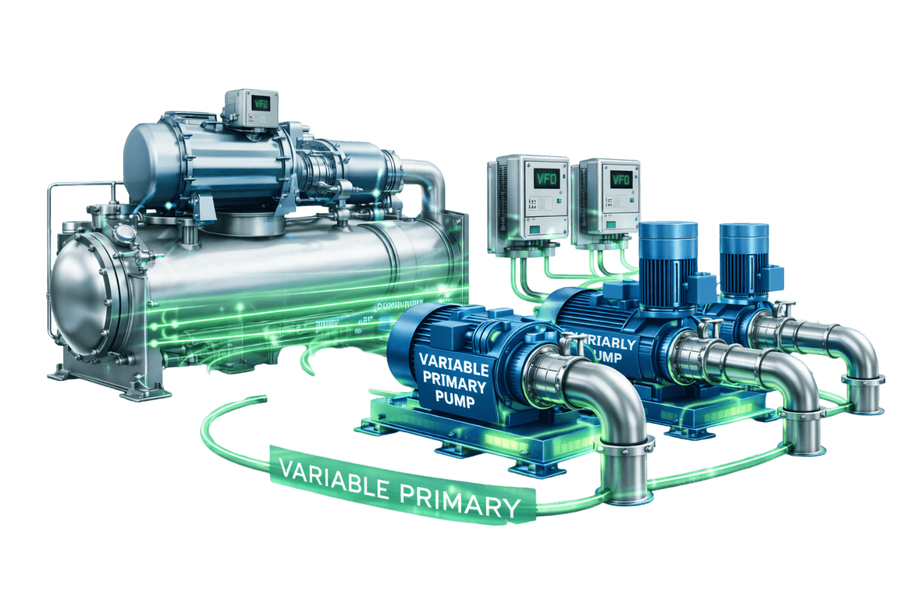
Variable Primary Flow Systems
Learn More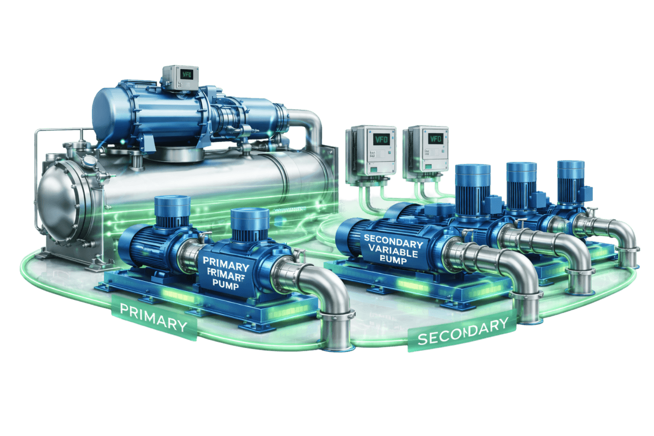
Primary–Secondary Variable Flow Systems
Learn More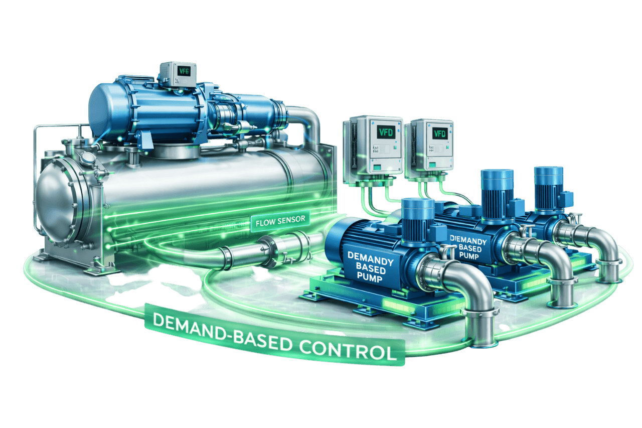
Demand-Based Pump Control Systems
Learn More
Pressure Independent Control Valve (PICV) Based Distribution
Learn MoreFrequently Asked Questions
Q1. What is a multi-pump variable speed configuration?
A multi-pump variable speed configuration uses two or more pumps with VFDs, usually in parallel, to share a pumping duty. A controller decides how many pumps run and at what speed. The combined output matches demand while each pump operates efficiently.
Q2. How do multiple variable speed pumps work together?
A lead pump runs alone at low demand and speeds up as demand rises. When it nears its limit, another pump stages on, and all running pumps operate at the same speed. As demand falls, the pumps slow down together and stage off one at a time.
Q3. Why use multiple smaller pumps instead of one large pump?
Multiple smaller pumps offer wider turndown, better efficiency at low loads, built-in redundancy with a smaller standby pump, and maintenance without shutdown. Near design load, a single large pump can be equally efficient, so the best choice depends on your load profile.
Q4. Should every pump have its own VFD?
For most HVAC and process systems, yes. One VFD per pump allows speed matching, smooth staging and soft starting. It also provides redundancy, since a drive failure affects only one pump. A common VFD, or one VFD with fixed-speed assist pumps, costs less but compromises control and reliability.
Q5. Can one VFD control multiple pumps?
Yes. One drive can run several identical motors at the same speed, each with its own overload protection, or switch between pumps through contactors. The whole set then depends on one drive, and pumps cannot be added to a running drive without ramping down. This approach suits smaller, non-critical systems.
Q6. What is the difference between parallel and series pump operation?
In parallel, pumps share the same head and their flows add, which suits systems needing variable or high flow. In series, pumps share the same flow and their heads add, which suits high head applications. Most HVAC multi-pump systems use parallel pumps.
Q7. How are pumps staged on and off in a multi-pump VFD system?
A pump is staged on when the running pumps exceed a speed or flow threshold for a set time, or when adding a pump improves efficiency. A pump is staged off when the remaining pumps can carry the load. Deadbands, time delays and ramp rates keep every transition smooth.
Q8. Why should parallel pumps run at the same speed?
Identical pumps at equal speed share flow evenly and operate at the same point on their curves. If one runs slower, the others can push it towards shut-off, where it may deadhead, overheat and suffer seal and bearing damage.
Q9. What is BEP-based pump staging?
BEP-based staging adds or removes pumps to keep each running pump within a flow band around its best efficiency point. It maximizes parallel pump efficiency, reduces vibration and extends pump life.
Q10. Should pumps in parallel be the same size?
Usually, yes. Identical pumps share flow evenly, simplify control and allow interchangeable spares. Unequal sizes, such as a small jockey pump for night loads, can save energy. They need careful staging so the smaller pump is not overpowered when both run.
Q11. How many pumps are required in a multi-pump system?
It depends on the load profile, turndown, redundancy needs, space and budget. HVAC plants commonly use 2 × 100%, 3 × 50% or 4 × 33% arrangements, each with a standby. Packaged booster sets commonly use two to six pumps.
Q12. What happens if a VFD fails in a multi-pump system?
With individual VFDs, the controller removes the affected pump, starts the next available pump and raises an alarm, so the plant keeps running. Where specified, a bypass starter can also run the pump at fixed speed, with safeguards against over-pressurizing the system.
Q13. How much energy can a multi-pump variable speed system save?
Converting fixed-speed parallel pumps to variable speed operation with proper staging commonly saves around 30–50% of pumping energy where loads vary. Compared with a single large VFD pump, the additional savings come mainly at low load and depend on your load profile. We estimate savings from measured site data.
Q14. What is the minimum speed for pumps running on VFD?
It depends on the pump, motor and system. On 50 Hz supplies, minimum speed is often set around 20–30 Hz. The correct value must keep each pump above its minimum continuous stable flow, maintain motor cooling and generate the required control head. For primary pumps, it must also protect chiller minimum flow.
Q15. Is a multi-pump variable speed configuration suitable for data centers and hospitals?
Yes. Critical facilities benefit from N+1 pumps, individual drives, automatic changeover and redundant sensors, so no single failure interrupts cooling. Staging keeps energy use under control while standby capacity stays ready.
Q16. What are common problems in multi-pump variable speed systems?
Common problems include:
- frequent staging
- unequal pump speeds
- deadheading
- VFD trips
- cavitation at runout
- check valve failures
Most trace back to staging thresholds, tuning, pump mismatch or piping layout, and all can be corrected.
Q17. Can VFDs be added to existing parallel pumps?
In most cases, yes. We check motor suitability, pump curves, panel space and harmonics. We then add a drive to each pump with a common speed control and automatic staging strategy. Pumps can be converted one at a time while the plant stays in service.
Q18. What maintenance does a multi-pump variable speed system need?
It needs regular VFD checks, pump and motor inspections, check valve and strainer maintenance, sensor calibration, and reviews of staging and rotation performance. A structured AMC keeps every pump healthy and the staging efficient.
Q19. What information is needed for a multi-pump variable speed system quotation?
We need:
- pump schedule and current configuration
- chiller details and system schematic
- control method and operating hours
- electrical SLD
- plant room drawings or photos
- tariff and any known problems
Our engineers can collect missing data during a site visit.
Q20. Does Compress India design and install multi-pump variable speed systems?
Yes. Compress India delivers complete multi-pump variable speed solutions for facilities in Mumbai, across Maharashtra and throughout India. Our scope covers:
- hydraulic design
- pump and VFD selection
- header and plant room layout
- electrical panels
- staging logic and BMS integration
- installation and commissioning
- retrofits and AMC