Variable Primary Flow Systems
(Design, Installation, Commissioning, Retrofit & Lifecycle Support for Chilled Water Pumping Systems)
Variable Primary Flow Systems – Chilled Water Plant Engineering & Execution
Compress India designs, builds, and supports variable primary flow systems for chilled water plants of every scale. We take responsibility for the complete lifecycle:
- Chiller compatibility review and hydraulic design
- Selection of variable speed primary pumps, VFDs, flow meters, and bypass valves
- Plant room piping and chiller isolation
- Control sequence engineering and BMS integration
- Testing, balancing, and flow transient testing
- Retrofits and AMC
The result is a leaner plant with fewer pumps and lower pumping energy, with chillers that stay protected at every load.
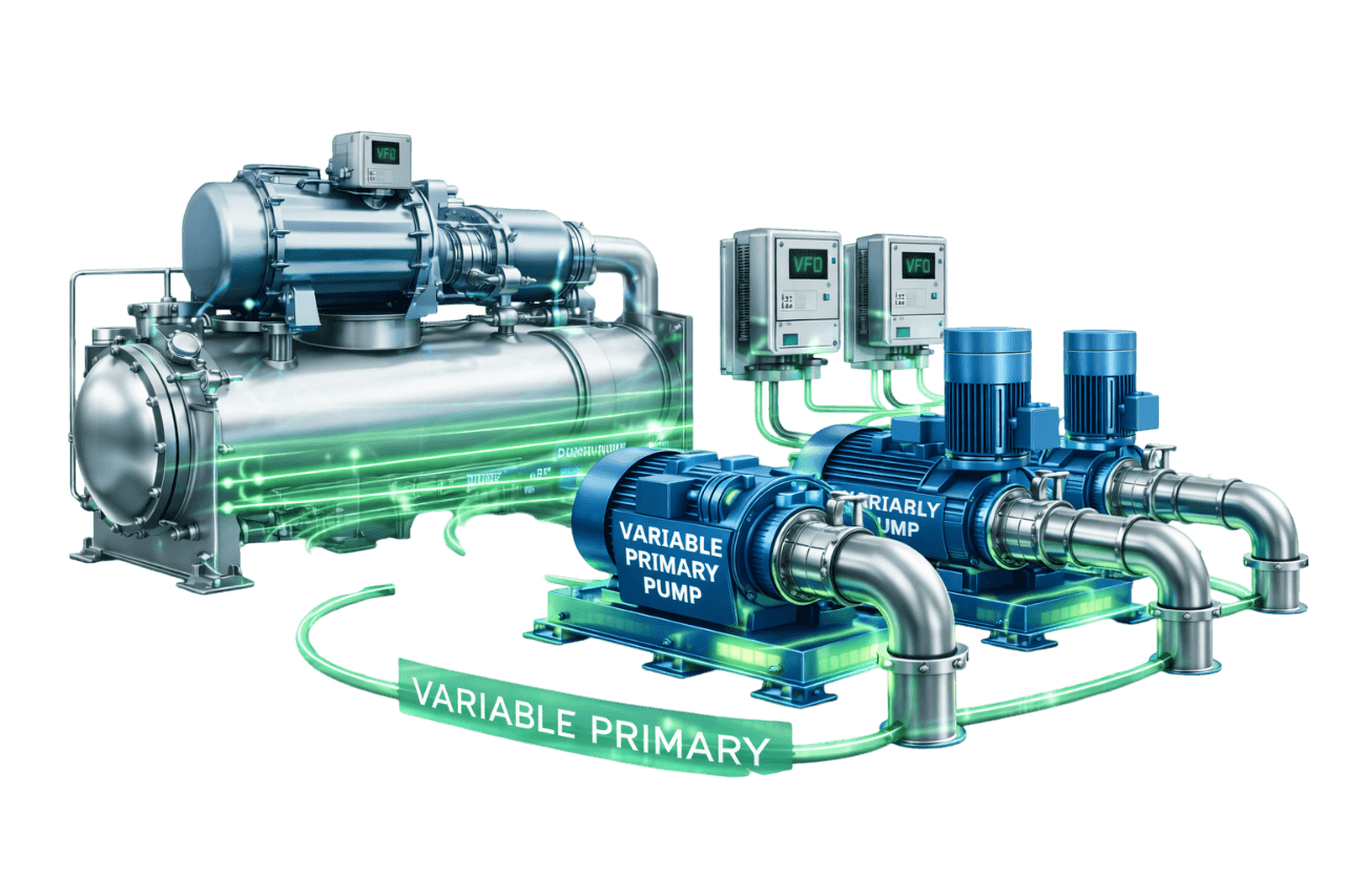
A variable primary flow design removes an entire set of pumps from the chilled water plant. One set of VFD pumps does the work that primary and secondary pumps share in a conventional plant. Less equipment means less plant room space, fewer motors to maintain, and lower pumping power throughout the year.
The trade-off is precision. A VPF plant depends on four things:
- Accurate flow measurement
- A correctly sized bypass
- Chillers that accept changing flow
- Control sequences that handle staging smoothly
When these are right, VPF is one of the most efficient pumping arrangements available. When they are not, chillers trip and the savings disappear. Compress India's HVAC execution team engineers and commissions every detail so your plant delivers the performance it was designed for.
What Is a Variable Primary Flow (VPF) System?
What is variable primary flow? It is a chilled water pumping arrangement in which a single set of variable speed pumps circulates water through the chillers and all the way out to the building loads. There is no separate secondary pump set and no decoupler.
A variable primary flow chilled water system has four defining features:
- Variable speed primary pumps with VFDs serve both the chillers and the distribution network.
- Flow through each chiller evaporator varies with load, within limits set by the chiller manufacturer.
- Two-way control valves at AHUs and FCUs vary the flow each load draws.
- A minimum flow bypass valve protects the chillers when building demand drops below chiller minimum flow.
A typical variable primary flow system diagram contains these elements:
- Chillers connected in parallel between a supply header and a return header, each with a motorized isolation valve
- Headered VFD pumps feeding the chillers from the return side
- A chilled water flow meter measuring chiller flow
- A short bypass line with a modulating valve linking the supply header back to the return header inside the plant room
- Distribution piping running to the loads, with a differential pressure sensor at the most demanding circuit
VPF system HVAC applications range from single office towers to large hospitals, malls, and campuses.
Why Chiller Plants Are Moving to Variable Primary Flow
Why use variable primary flow system designs? Several developments have made VPF a mainstream choice:
- Modern chillers accept variable flow. Advanced microprocessor controls and VFD compressors let chillers respond to changing evaporator flow within published limits.
- Energy codes favour variable flow. Building energy codes and standards push designers toward variable speed pumping and lower pump power.
- Fewer pumps, less space. Removing a pump set saves plant room area, electrical infrastructure, and maintenance effort.
- Better handling of low delta T. VPF can push more water through running chillers instead of starting an extra chiller when return temperature drops.
- Dependable instrumentation. Accurate flow meters, reliable VFDs, and modern chiller plant managers make VPF sequences robust.
How a Variable Primary Flow System Works
How does variable primary flow work from minute to minute? The plant runs through six coordinated stages.
1. Variable Speed Primary Pumps Serving Chillers and Load
One set of VFD pumps draws water from the return header, pushes it through the running chillers, and delivers it all the way to the most remote coil. These variable speed primary pumps are sized for the full system head: plant, distribution, and loads combined.
2. Variable Flow Through Chiller Evaporators
As the building load falls, less water circulates, and the chiller evaporator flow rate falls with it. Each chiller's controls hold the leaving water temperature steady while flow changes, as long as flow stays within the manufacturer's minimum and maximum limits.
3. Two-Way Control Valves at AHUs & FCUs
Each coil has a two-way modulating valve controlled by space or supply air temperature. When a zone needs less cooling, its valve partially closes and reduces the water it draws.
4. Differential Pressure–Based Pump Speed Control
A differential pressure sensor across the most demanding circuit tells the pump VFDs how hard to work. As valves close, pressure rises and the pumps slow down. As valves open, the pumps speed up.
5. Minimum Flow Bypass Valve Operation
At very light loads, total building demand can fall below the minimum flow a running chiller needs. The minimum flow bypass valve then opens just enough to circulate the difference through the chiller, and closes again as demand recovers.
6. Chiller Staging Based on Load and Flow
The plant controller decides when to add or remove chillers based on calculated load, total flow, and supply temperature. Isolation valves open and close slowly during staging, so running chillers are not hit by sudden flow changes.
Main Components of a Variable Primary Flow System
- Chillers rated for variable evaporator flow
- Variable speed primary pumps with individual VFDs
- Motorized isolation valve on each chiller
- Chilled water flow meter or evaporator differential pressure transmitters
- Minimum flow bypass line with a modulating control valve
- Two-way control valves at all AHUs and FCUs
- Differential pressure sensors at the index circuit
- Chilled water supply and return temperature sensors
- Supply and return headers
- Strainers, check valves, isolation valves, and flexible connectors
- Expansion tank, air separator, and water treatment system
- Chiller plant manager and BMS interface
- Insulated chilled water piping
Minimum Flow Bypass in VPF Systems
Why a Minimum Flow Bypass Is Required
Every chiller needs a minimum flow through its evaporator, for three reasons:
- To keep tube velocity high enough for effective heat transfer
- To maintain stable temperature control
- To guard against freezing
At light load, the building may draw less than this minimum. The variable primary flow bypass valve makes up the difference by recirculating chilled water through the chiller without sending it out to the building.
Bypass Valve Sizing and Selection
A well-designed bypass valve meets these criteria:
- Sized for the minimum flow of the largest chiller in the plant
- Selected to control smoothly at that flow with the pressure available across the bypass
- Fast enough to protect the chiller, but not so oversized that it hunts at small openings
- Defined fail position, agreed at design stage to suit the plant's protection philosophy
A simple differential pressure bypass valve, which opens at a fixed pressure setting, is common in small constant-speed systems. In a VPF plant, however, the bypass is best controlled on measured chiller flow, because differential pressure alone does not tell the controller how much water is passing through the evaporators.
Bypass Location – Near Plant vs End of Loop
Near the plant (preferred): The bypass connects the supply and return headers inside the plant room. This location offers:
- Fast response
- Lower pumping energy, because bypass water does not travel the whole distribution loop
- Easy access for maintenance
End of loop: A bypass at the far end of the distribution network keeps remote piping cold, but it has drawbacks:
- Slower response
- Added pumping energy
- Harder to control on chiller flow
Three-way valves at the ends of branches are sometimes used as a crude bypass. This is not recommended, because they waste flow continuously and depress delta T.
Bypass Control Using Flow Meter or Evaporator DP
The bypass valve modulates to keep chiller flow at or above the combined minimum of the running chillers, plus a small safety margin. Chiller flow is measured in one of two ways:
- A flow meter in the chiller header, measuring total flow through the evaporators
- Differential pressure transmitters across each evaporator, calibrated to flow, since flow varies with the square root of pressure drop
When measured flow approaches the minimum, the valve opens. When building demand rises, it closes smoothly.
Chiller Requirements for Variable Primary Flow
Minimum and Maximum Evaporator Flow Limits
The manufacturer sets both the chiller minimum flow rate and the maximum flow rate, based on evaporator tube velocity:
- Below the minimum, heat transfer suffers and control becomes unstable.
- Above the maximum, pressure drop and tube erosion increase.
The wider the range between minimum and maximum flow, the better a chiller suits VPF. Adding evaporator passes raises tube velocity. This lowers the minimum flow as a share of design flow, but it also increases pressure drop. We evaluate this trade-off at the chiller selection stage.
Allowable Rate of Flow Change
Chillers also limit how fast evaporator flow may change, usually stated as a percentage of design flow per minute. Rapid swings can upset leaving water temperature control and trip the chiller. Pump ramp rates, valve stroke times, and staging sequences must all respect this limit.
Chiller Controls Compatibility
Chiller controllers must respond quickly to changes in flow and entering water temperature. They should also communicate status, flow, and alarms to the plant manager. Older chillers may need a controls upgrade before a VPF conversion.
Suitability of Centrifugal, Screw & Scroll Chillers for VPF
- Centrifugal chillers: Large evaporators and advanced controls make them strong VPF candidates. VFD centrifugal chillers are especially well suited.
- Screw chillers: Generally good candidates. The evaporator type and the controls determine the usable flow range.
- Scroll chillers: These often use brazed plate evaporators with small water volume, making them more sensitive to flow and temperature swings. Manufacturer limits and minimum system water volume must be checked, and a buffer tank is sometimes needed.
Minimum flow data for variable primary flow and rate-of-change limits must always come from the manufacturer for the specific chiller model selected.
Primary Pump Arrangements in VPF Systems
Headered Variable Speed Primary Pumps
Most VPF plants use headered pumps. All pumps discharge into a common header that feeds every chiller through motorized isolation valves.
Because the number of running pumps is independent of the number of running chillers, the controller can:
- Run the most efficient pump combination at every load
- Protect the whole group with a single standby pump
Dedicated Variable Speed Primary Pumps
Each chiller has its own VFD pump, and flow through each chiller is set by that pump's speed. This arrangement easily accommodates chillers of unequal size.
It has three drawbacks:
- Pump count must match chiller count.
- A pump failure takes its chiller offline unless a standby is provided.
- The pumps must be speed-coordinated so they share the distribution load properly.
Comparison Table – Headered vs Dedicated Pumps in VPF
| Parameter | Headered VFD Pumps | Dedicated VFD Pumps |
|---|---|---|
| Pump–chiller link | Any pump serves any chiller | One pump per chiller |
| Running pumps vs running chillers | Independent | Always equal |
| Chiller isolation valves | Required | Not always required |
| Flow control per chiller | Valves, balancing, and flow measurement | Its own pump speed |
| Unequal chiller sizes | Needs careful balancing | Straightforward |
| Standby coverage | One standby for the group | Per chiller or via crossover |
| Part-load pump efficiency | Excellent, with flexible pump staging | Good |
| Typical choice | Most VPF plants | Small or mixed-size plants |
Chiller Isolation Valves in VPF Systems
Motorized Isolation Valves for Each Chiller
In a headered VPF plant, every chiller has a motorized isolation valve on its evaporator, usually a butterfly valve. When a chiller is off, its valve stays closed, so water cannot slip through the idle machine uncooled and warm the supply. The valves must seal tightly and report their position to the controller.
Slow-Acting Valve Operation During Staging
When a new chiller's valve opens, water that was flowing through the running chillers suddenly divides among more machines. Flow in the running chillers can drop sharply, possibly below their minimum or faster than their allowable rate of change.
These techniques spread the change out over time:
- Slow-stroke actuators on the isolation valves
- A temporary increase in pump speed
- Pre-opening the bypass valve
The same care applies when a chiller is taken offline.
Flow Measurement in VPF Systems
Electromagnetic / Ultrasonic Flow Meters
- Electromagnetic (magnetic) flow meters offer high accuracy, no moving parts, and negligible pressure drop. They are a first-choice chilled water flow meter for new VPF plants.
- Ultrasonic flow meters come in inline and clamp-on versions. Clamp-on meters can be installed without cutting pipes, which suits retrofits, but their accuracy depends heavily on pipe condition and installation quality.
Evaporator Differential Pressure Measurement
A DP transmitter across each evaporator provides a low-cost flow signal, because flow varies with the square root of pressure drop. Accuracy depends on two factors:
- Calibration against known flows during commissioning
- Tube condition, since fouling changes the relationship between pressure drop and flow
For this reason, the calibration should be re-verified periodically.
Flow Meter Location & Accuracy
A flow meter needs a full pipe and the straight upstream and downstream pipe lengths specified by its manufacturer. It should measure flow through the chillers, not just flow to the building. This way, the controller knows the true chiller flow even when the bypass is open.
Meters are verified during TAB and should be checked again at planned intervals.
Pump Speed Control in Variable Primary Flow Systems
Differential Pressure Control of Primary Pumps
The pump VFDs hold a DP set point at the remote circuit, and the DP signal drives pump speed. Chiller minimum flow is protected separately by the bypass valve. Keeping these two control loops distinct and properly tuned is essential for stable variable primary flow with VFD operation.
DP Sensor Location – Index Circuit / Remote Point
The DP sensor goes at the hydraulically most demanding coil or near the end of the longest branch. Large buildings use several sensors, and the pumps respond to whichever one is furthest below its set point.
Differential Pressure Setpoint Reset
Rather than holding a fixed DP, the controller works as follows:
- It trims the set point down while every control valve is partly closed.
- It raises the set point only when a valve approaches fully open.
Lower DP means lower pump speed and less throttling at the valves, which adds further savings.
Parallel Pump Staging with VFDs
Parallel VFD pumps run at matched speeds:
- A pump is added when the running pumps approach full speed.
- A pump is removed when fewer pumps can carry the flow near their best efficiency point.
Time delays prevent pumps from cycling on and off.
Chiller Staging Strategies in VPF Systems
Load-Based Chiller Staging
The controller calculates the actual cooling load from flow and delta T, then compares it with the capacity of the running chillers:
- A chiller is added when load approaches running capacity for a sustained period.
- A chiller is removed when the remaining machines can carry the load with a comfortable margin.
Flow-Based Chiller Staging
In VPF, flow is a staging trigger in its own right:
- Stage up on flow: If flow per chiller approaches the maximum evaporator flow, another chiller is added even when load is moderate. This is common during low delta T conditions.
- Stage down on flow: A chiller is removed only when the remaining chillers can carry the total flow below their maximum.
Supply Temperature–Based Staging
If chilled water supply temperature stays above set point by a set margin, the running chillers have reached their limit and another chiller starts. This acts as a safety net behind the load and flow triggers.
Managing Flow Transients During Chiller Start/Stop
Smooth staging relies on:
- Raising pump speed or opening the bypass before a new chiller's valve opens
- Slow-opening and slow-closing isolation valves
- Holding other control loops steady during the staging event
- Minimum run and minimum off timers for every chiller
Benefits of Variable Primary Flow Systems
Lower Pumping Energy
Only one set of pumps runs, and it slows down whenever load falls. No constant-speed primary pumps are left running at full speed regardless of demand.
Fewer Pumps and Reduced Plant Room Space
Removing a pump set eliminates pumps, motors, starters, piping, valves, and the floor area they occupy.
Lower Initial Cost Compared to Primary-Secondary
Fewer pumps and less piping usually offset the added cost of flow meters, bypass valves, isolation valves, and controls.
Better Chilled Water Delta-T Management
With no decoupler carrying surplus supply water back to the chillers, return water temperature stays closer to design.
Improved Chiller Plant Efficiency (kW/TR)
When delta T drops, VPF can push more flow through the running chillers, up to their maximum. This avoids starting another chiller at part load, keeps machines better loaded, and improves plant kW/TR.
Flexible Chiller–Pump Combinations
With headered pumps, any combination of pumps can serve any combination of chillers.
Easy Future Expansion
New chillers and pumps connect to the existing headers through isolation valves and are simply added to the staging logic.
Limitations & Design Challenges
Variable primary flow advantages and disadvantages should both be weighed before committing to a design. These are the main challenges.
Complex Control Sequences
Pump speed, bypass control, chiller staging, and valve sequencing must all work together precisely.
Chiller Minimum Flow Protection
If flow measurement or bypass control fails, chillers can trip on low evaporator flow.
Flow Transients During Chiller Staging
Opening a chiller's isolation valve can momentarily starve the chillers already running.
Bypass Valve Sizing and Control Issues
Oversized or poorly tuned bypass valves hunt, waste pump energy, and depress delta T.
Need for Skilled Operation & Commissioning
A VPF plant performs only as well as its commissioning and its operators. Manual overrides that bypass the sequences can trip chillers.
Low Delta-T Effects in VPF Systems
VPF tolerates low delta T better than primary-secondary designs, but it is not immune. Chronically low delta T still raises flow and pump energy, and eventually brings more chillers online.
Compress India addresses each of these challenges through design, commissioning, and operator training.
Variable Primary Flow vs Primary-Secondary (Constant Primary – Variable Secondary) System
In a conventional plant, the primary pump and secondary pump in HVAC systems each serve one loop:
- A constant-speed chiller primary pump holds fixed flow through each chiller.
- VFD secondary pumps serve the building through a decoupler.
Here is how variable primary flow vs primary secondary compares:
| Parameter | Primary-Secondary (CPVS) | Variable Primary Flow |
|---|---|---|
| Pump sets | Two | One |
| Chiller evaporator flow | Constant | Variable within limits |
| Hydraulic separation | Decoupler | Minimum flow bypass |
| Pump energy at part load | Primary pumps stay at full speed | All pumps slow down |
| Response to low delta T | Extra chillers started | Running chillers can take more flow |
| Plant room space | More | Less |
| First cost | Higher | Usually lower |
| Instrumentation | Basic | Flow meters, valve position feedback |
| Control complexity | Lower | Higher |
| Chiller compatibility | Any chiller | Chillers rated for variable flow |
| Operator skill required | Moderate | Higher |
Is variable primary flow better than primary secondary? For many plants with compatible chillers and a capable operations team, VPF delivers lower energy use and lower first cost.
The variable primary flow vs constant primary variable secondary decision is not one-size-fits-all, though. An HVAC primary secondary pump design remains the safer choice in three situations:
- Chillers cannot accept variable flow
- Operators prefer simplicity
- The distribution network is very large and heavily zoned
Compress India evaluates both options before recommending either.
Variable Primary Flow vs Constant Primary Flow System
A constant primary flow system uses constant-speed pumps and three-way valves. It circulates the same flow at every load, which leads to:
- High pump energy
- Low delta T at part load
- More chillers running than the load requires
A VPF system replaces the three-way valves with two-way valves and adds VFD pumps, so flow tracks the actual load. Converting a constant flow plant to VPF is one of the highest-impact energy upgrades available for older chilled water systems.
Variable Primary Flow vs Variable Primary with Secondary Loop
A variable primary with secondary loop design adds a second set of VFD pumps to serve distribution zones. That extra set is justified in:
- Large campuses
- Buildings whose zones have very different head requirements
- Sites with long distribution runs
A VPF-only plant is simpler and less expensive. It suits compact plants and single buildings where one pump set can reach every load efficiently.
ECBC & ASHRAE 90.1 Considerations for Variable Flow Systems
India: ECBC and its successor, ECSBC 2024
India's Energy Conservation Building Code has been updated as the Energy Conservation and Sustainable Building Code (ECSBC) 2024.
- What changed: Compared with ECBC 2017, the new code slightly tightens energy efficiency thresholds and adds sustainability measures.
- Who it applies to: Commercial and office buildings with a connected load of 100 kW or more, or a contract demand of 120 kVA or more.
- Where it applies: The code becomes mandatory where a state adopts it, so applicability depends on project location.
- Compliance tiers: There are three levels, ECSBC, ECSBC+ and Super ECSBC. The base level is mandatory and the higher tiers are voluntary.
For chilled water plants, three points matter most:
- The prescriptive (standardized) compliance path includes dedicated sections on pumps and on variable flow hydronic systems.
- Central chilled water plants can instead follow a Total System Efficiency route. This route assesses chillers, chilled water pumps, condenser water pumps, and cooling tower fans together against tiered thresholds.
- Testing and balancing is a mandatory HVAC requirement, and energy-efficient motors are mandatory under the electrical chapter.
ASHRAE Standard 90.1
Recent editions of ASHRAE Standard 90.1 set clear rules for hydronic variable flow:
- Variable flow design: Chilled- and hot-water systems with three or more modulating control valves must be designed for variable flow. They must be able to reduce pump flow to the larger of 25% of design flow or the equipment manufacturer's minimum.
- Pump power at part load: Pumps above a threshold motor size must draw no more than 30% of design power at 50% of design flow, which in practice means variable speed control.
- Primary pump exemption: Primary pumps in a primary/secondary system are exempt from the variable flow requirement. In a VPF plant, the primary pumps are also the distribution pumps, so they are designed to the variable flow provisions from the start.
- Control sequences: Informative notes point to ASHRAE Guideline 36 for detailed sequences, including differential pressure reset based on valve position and chiller flow isolation and staging.
Code requirements vary by edition and by local adoption, so the version applicable to your project should be confirmed with your design consultant. Compress India prepares VPF designs with these provisions in mind, so your consultant has the pump, VFD, and control data needed for compliance submissions.
Variable Primary Flow Systems for HVAC
In comfort cooling, loads change constantly with occupancy, sun, and weather. A VPF plant with two-way valves and VFD pumps follows those changes closely, whether it serves offices, malls, hotels, or hospitals. The building receives exactly the chilled water it needs, pumps slow down during the long part-load hours, and chillers stay better loaded.
Variable Primary Flow Systems for Industrial & Process Cooling
VPF works well for process loads that vary with batches, shifts, or production rates. Where process loads are nearly constant, pumping savings are smaller, and a simpler arrangement may be more economical.
For critical processes, Compress India designs VPF plants with:
- Robust minimum flow protection
- Redundant flow measurement
- Conservative staging
Where needed, we also add separate loops or heat exchangers to isolate sensitive equipment.
Applications of Variable Primary Flow Systems
Commercial Buildings & Office Complexes
Daily occupancy swings make VPF a natural fit, with large pumping savings during evenings, weekends, and mild weather.
Shopping Malls
Long operating hours and fluctuating footfall reward variable flow and flexible chiller staging.
Hospitals
VPF suits hospitals when it is paired with N+1 pumps, dependable flow measurement, and thoroughly commissioned sequences.
Data Centers
VPF is used in data centers where redundant flow meters, fail-safe bypass control, and rigorous transient testing protect continuous IT cooling.
Pharmaceutical Facilities
VPF serves clean rooms and process areas efficiently, with conservative staging to hold tight temperature tolerances.
Manufacturing Plants
Shift-based and batch loads benefit from pumps that slow down when production eases.
Hotels
Occupancy-driven loads in guest rooms, banquets, and restaurants suit variable flow well.
Airports & Metro Systems
Large, variable loads across terminals and stations benefit from lower pumping energy. Very long networks may call for a secondary loop.
IT Parks & Campuses
VPF works well for compact central plants. For widely spread campuses, we evaluate adding secondary or distributed pumping.
District Cooling Plants
Variable primary pumping at the central plant, combined with building-level pumping or heat exchangers, delivers efficient distribution to many buildings.
Variable Primary Flow in Multi-Chiller Plants with Centrifugal & Screw Chillers
Multi-chiller plants gain the most from VPF, because chiller staging and pump staging can be optimized independently.
- Equal-sized chillers simplify VPF design, since every machine shares the same minimum and maximum flow limits.
- Unequal chillers need per-chiller flow limits in the control logic, careful balancing, and ideally individual flow measurement.
VFD centrifugal and screw chillers pair especially well with variable primary pumping, because they stay efficient across wide load and flow ranges. Compress India stages each chiller according to its own efficiency curve and flow limits.
System Design & Sizing
This section serves as a practical variable primary flow design guide for the key calculations.
Chilled Water Flow Calculation (GPM / m³/hr per TR)
- Imperial: Flow (GPM) = TR × 24 ÷ ΔT (°F)
- Metric: Flow (m³/hr) = TR × 3.024 ÷ ΔT (°C)
- Per kWr (as used in Indian codes): At a 5.5°C difference, flow is roughly 0.043 L/s per kWr, or about 0.153 L/s per TR.
For example, a 500 TR chiller at a 10°F (5.5°C) difference needs about 1,200 GPM.
Primary Pump Head Calculation
In VPF, the primary pumps must overcome the entire system resistance, because no secondary pumps share the work. The head calculation includes:
- Chiller evaporator pressure drop at design flow
- Plant piping, headers, and valves
- Distribution piping to the index circuit
- Coil, control valve, and balancing losses
- A safety margin
At part load, evaporator and piping losses fall roughly with the square of flow, which is where much of the pumping saving comes from.
Chiller Minimum Flow and Bypass Flow Calculation
The bypass is sized for the minimum flow of the largest chiller. For example, suppose the 500 TR chiller above has a manufacturer minimum of, say, 40% of design flow. The bypass must then handle about 480 GPM.
The controller's minimum flow set point is the sum of the minimum flows of all running chillers, plus a small safety margin.
Chilled Water Delta-T Selection
Many plants are designed around a 5.5°C (10°F) difference. A wider delta T reduces flow, pipe sizes, and pump power, provided coils and valves are selected to achieve it in real operation.
Header and Pipe Sizing
Headers are sized for low velocity so flow divides evenly among parallel chillers. Distribution pipes balance first cost against lifetime pumping energy.
Number of Pumps & Redundancy Selection
Two to four duty pumps plus a standby is typical. The final choice depends on:
- Flow range
- Part-load efficiency
- Redundancy needs
Pump Selection Criteria
End-Suction vs Split-Case Pumps
- End-suction pumps suit small and medium plants and offer easy back pull-out servicing.
- Split-case pumps handle large VPF plant flows at high efficiency.
Inline Pumps
Inline pumps save floor space and simplify piping, and they work well in compact plant rooms.
Pump Efficiency and Best Efficiency Point (BEP)
Pumps are selected so that their operating points stay near BEP as speed falls under DP control. We also check performance at minimum speed and minimum flow.
Motor & VFD Selection
We specify:
- Premium-efficiency motors
- Individual VFDs with appropriate minimum speed settings
- Harmonic mitigation where required
Every pump gets its own drive for reliability.
Piping Layout & Plant Room Arrangement
Primary Header Piping
The primary flow pipe (the supply header leaving the chillers) and the return header feeding the pumps are laid out with symmetrical branch connections and low velocity. Straight runs are reserved for flow meters.
Minimum Flow Bypass Line Piping
The bypass connects the supply header, downstream of the chillers, to the return header, upstream of the pumps. The bypass valve has isolation valves on both sides for maintenance, and the line is kept short and accessible.
Chiller Isolation Valves, Strainers & Check Valves
The key fittings are:
- A motorized isolation valve on each chiller
- A suction strainer on each pump
- A check valve on each pump discharge, which is essential in headered arrangements to prevent backflow through idle pumps
Flow Meter and Sensor Placement
Flow meters are installed with the required straight pipe lengths. Temperature sensors sit in properly located thermowells, and DP transmitters connect at the evaporator nozzles.
Insulation of Chilled Water Piping
Closed-cell insulation with a continuous vapour barrier and protective cladding prevents heat gain and condensation.
Controls, Automation & BMS Integration
A typical variable primary flow control sequence includes:
- 1. Primary pumps modulate on differential pressure, with set point reset.
- 2. The bypass valve modulates to keep chiller flow above the combined minimum.
- 3. Chillers stage on load, flow, and supply temperature, with time delays.
- 4. Isolation valves open and close slowly, coordinated with pump speed.
- 5. Safe fallback actions apply if a flow meter or sensor fails.
Chiller Staging Logic
The staging logic combines load, flow, and temperature triggers with minimum run and off timers, so chillers are added and removed without short cycling.
Primary Pump Speed Control Logic
Pump speed follows the lowest-margin DP sensor, with limits on speed and ramp rate to respect chiller flow change limits.
Minimum Flow Bypass Control Logic
The bypass opens only as chiller flow nears its minimum, and it is tuned for stable control without hunting.
Chiller Isolation Valve Sequencing
Each valve opens before its chiller starts and closes after it stops. Pump speed or bypass position is adjusted in advance to smooth the flow change.
Chiller Plant Manager & BMS Integration
Compress India integrates the plant with a chiller plant manager and your BMS for live monitoring, alarms, trends, and energy reports.
Energy Efficiency & Power Consumption
Pumping Energy Calculation
Pump input power (kW) = Flow (m³/hr) × Head (m) ÷ (367 × Pump Efficiency × Motor Efficiency × VFD Efficiency).
Pump power falls steeply as speed drops. This is where most variable primary flow energy savings come from during part-load hours.
Plant kW/TR Calculation
Plant kW/TR = (chiller kW + pump kW + cooling tower fan kW) ÷ cooling delivered in TR, where TR = Flow (m³/hr) × ΔT (°C) ÷ 3.024.
ECSBC's Total System Efficiency approach uses a related annual measure. It divides the yearly electricity use of the water-cooled chilled water plant equipment by the thermal energy delivered by the chillers.
Plant Optimization Strategies
- Apply DP set point reset based on valve position.
- Keep the bypass closed during normal operation.
- Stage chillers on efficiency curves and flow limits.
- Push more flow through running chillers before starting another one.
- Restore design delta T through coil cleaning and valve correction.
- Reset chilled water supply temperature based on load.
- Optimize condenser water temperature and tower fan speed.
Installation of Variable Primary Flow Systems
Our execution teams handle the complete installation:
- Pump foundations and alignment
- Header and bypass piping
- Flow meter installation with the required straight runs
- Motorized isolation valves
- DP and temperature sensors
- Insulation
- VFD wiring
- Controls
All work follows approved drawings and quality checkpoints.
Testing, Balancing & Commissioning (TAB)
Flow Meter Calibration
We verify each flow meter or evaporator DP signal against measured flows and correct calibration before handover.
Bypass Valve Testing
We confirm the bypass opens at the correct minimum flow, controls smoothly without hunting, and responds correctly to simulated low-load conditions.
Chiller Staging & Flow Transient Testing
We stage chillers up and down under real conditions, while monitoring:
- Flow in the running chillers
- Rate of flow change
- Supply temperature
This proves that no chiller trips during staging. You receive complete TAB and sequence test reports.
Maintenance & AMC for Variable Primary Flow Systems
Our VPF-focused AMC includes:
- Flow meter and DP transmitter verification
- Bypass valve and actuator checks
- Isolation valve seal and stroke tests
- Pump vibration, bearing, and seal inspection
- VFD servicing
- Chiller tube cleaning, which also keeps evaporator DP readings accurate
- Water treatment monitoring
- Periodic review of staging and reset sequences
Common Problems & Troubleshooting
Chiller Trips Due to Low Evaporator Flow
The usual causes are:
- Wrong minimum flow set points
- Failed flow signals
- Slow bypass response
- Aggressive staging
We correct sequences, instrumentation, and tuning.
Bypass Valve Hunting
Oversized valves or aggressive tuning cause oscillation. Resizing the valve or retuning the loop restores stable control.
Flow Surges During Chiller Staging
Fast-acting isolation valves or missing pre-staging steps cause flow spikes. Slower actuators and revised sequences smooth the transitions.
Low Delta-T
The common causes are:
- Dirty coils
- Leaking or oversized control valves
- Leftover three-way valves
- Incorrect set points
We trace and correct each one.
Flow Meter and Sensor Errors
Insufficient straight runs, drift, fouled evaporators, or wiring faults distort readings. We verify, relocate, or recalibrate as needed.
VFD Hunting / Unstable DP Control
Poor PID tuning or badly placed sensors make pumps surge. Proper tuning and sensor relocation stabilize operation.
Retrofitting & Converting to Variable Primary Flow
Converting Primary-Secondary Systems to VPF
A typical conversion involves:
- Removing one pump set, often retaining and re-selecting the more suitable set as the new VPF pumps
- Adding chiller isolation valves, flow measurement, and a minimum flow bypass
- Reworking the decoupler
- Upgrading the controls
Converting Constant Flow Systems to VPF
This conversion replaces three-way valves with two-way valves, adds VFDs, installs a bypass and flow measurement, and implements VPF sequences.
Adding VFDs to Existing Primary Pumps
VFDs are installed on existing pumps where the pumps are suitable for variable speed operation, along with DP control and minimum speed settings.
Replacing Three-Way Valves with Two-Way Valves
This step is essential for any variable flow conversion. It restores delta T and enables real pumping savings.
Chiller Compatibility Check Before Conversion
Before any conversion, we review each chiller's:
- Minimum and maximum flow
- Allowable rate of flow change
- Controls
- Evaporator configuration
Where needed, we work with the manufacturer on controls upgrades.
Variable Primary Flow System Cost in India
The cost of a variable primary pumping system depends on:
- Plant size and number of chillers
- Pump type
- Flow instrumentation
- Controls
Compress India provides clear, itemized quotations covering design, supply, installation, and commissioning.
Factors Affecting Project Cost
- Total cooling capacity (TR) and flow rates
- Number and type of chillers
- Number of pumps and redundancy level
- VFDs and motor ratings
- Flow meters and DP transmitters
- Bypass valve and motorized isolation valves
- Chiller plant manager and BMS integration
- Header sizes, pipe lengths, and insulation
- New installation or conversion of a running plant
- Site access and project timeline
Information Required for a Quotation
- Facility type and application
- Cooling load and load profile
- Chiller make, model, and flow limits, where existing
- Plant layout and drawings
- Existing pumping arrangement, for retrofits
- Coil valve types (two-way or three-way)
- Design supply and return temperatures
- Redundancy requirements
- Scope: design, supply, installation, commissioning, retrofit, or AMC
- Location and timeline
Variable Primary Flow System Contractor in Mumbai
Compress India is an experienced variable primary flow system contractor in Mumbai. We deliver new VPF plants and conversions for:
- Commercial towers, malls, and hotels
- Hospitals and data centers
- Industrial facilities
Our Mumbai teams provide quick site assessments, fast mobilization, and reliable after-sales support.
Chilled Water Pumping Solutions in Mumbai, Navi Mumbai, Thane & Maharashtra
We design, install, and maintain VPF plants, VFD retrofits, and complete chilled water plant rooms across Maharashtra, including:
- Mumbai, Navi Mumbai, and Thane
- Pune and Nashik
- Aurangabad and Nagpur
Variable Primary Flow System Solutions Across India
Compress India supports VPF projects nationwide, including:
- New plants
- Conversions from primary-secondary and constant flow systems
- Energy optimization
- Long-term AMC
Why Choose Compress India for Variable Primary Flow Systems?
Hydraulic Design Expertise
We calculate full-system head, bypass sizing, and header design with precision.
Complete Chiller Plant Integration
Chillers, pumps, towers, valves, and controls are engineered as one system.
Pump, VFD & Flow Meter Selection Support
We choose equipment for efficiency, accuracy, and reliability.
Control Sequence Engineering
Our staging, bypass, and pump sequences are written and tuned for your specific plant and chillers.
Installation & Commissioning
Skilled teams install to specification and prove performance through flow transient testing.
Retrofit & Energy Optimization
We handle conversions from primary-secondary and constant flow systems with minimal downtime.
AMC & Lifecycle Support
Instrument verification, sequence reviews, and preventive maintenance keep your VPF plant performing year after year.
How to Select the Right Variable Primary Flow Design
- Do your chillers support variable evaporator flow? Confirm the minimum flow, maximum flow, and rate-of-change limits.
- Is the site compact or spread out? Compact plants suit VPF only. Large campuses may need a secondary loop.
- Are chillers equal or mixed in size? Mixed sizes need per-chiller flow limits and careful balancing.
- How critical is cooling? Plan redundant pumps and redundant flow measurement for critical facilities.
- How experienced is your operations team? VPF needs trained operators and well-documented sequences.
- Which code applies to your project? Consider ECSBC and ASHRAE 90.1 requirements early.
Our engineers assess each factor and recommend the design that balances energy savings, reliability, and cost.
Get a Variable Primary Flow System Solution from Compress India
Whether you are planning a new chilled water plant or converting an existing primary-secondary or constant flow system, Compress India delivers a variable primary flow system engineered for real-world savings and dependable chiller protection.
Connect with Our HVAC Execution Team
Share your project details for a technical discussion, site survey, and detailed quotation.
Related Systems Types & Components
Explore our comprehensive range of hydronic system configurations and components designed for efficient water distribution.
Primary–Secondary Variable Flow Systems
Learn More
Demand-Based Pump Control Systems
Learn More
Multi-Pump Variable Speed Configurations
Learn More
Pressure Independent Control Valve (PICV) Based Distribution
Learn MoreFrequently Asked Questions
Q1: What is a variable primary flow system?
It is a chilled water system in which a single set of variable speed pumps circulates water through the chillers and to the building loads, with flow through the chillers varying with demand.
Q2: How does a variable primary flow chilled water system work?
The system works through four coordinated controls:
- Two-way valves at the coils vary flow to each load.
- VFD pumps respond to differential pressure.
- A minimum flow bypass protects the chillers at low load.
- The controller stages chillers on load, flow, and temperature.
Q3: What is the difference between variable primary flow and primary-secondary systems?
Primary-secondary uses two pump sets, with constant flow through the chillers and a decoupler between the loops. VPF uses one variable speed pump set, with variable chiller flow and a minimum flow bypass.
Q4: Why is a minimum flow bypass valve required in VPF systems?
It keeps flow through running chillers above their minimum when building demand falls too low.
Q5: Where should the bypass valve be located in a VPF system?
Usually in the plant room, between the supply and return headers. This gives fast response and lower pumping energy.
Q6: Can all chillers operate with variable evaporator flow?
No. Each chiller's minimum flow, maximum flow, rate-of-change limits, and controls must be confirmed with the manufacturer.
Q7: What is the minimum evaporator flow for chillers in VPF systems?
It varies by model and evaporator design. It is set by the manufacturer based on tube velocity and must be taken from the selected chiller's data.
Q8: What is the allowable rate of flow change for chillers?
It is the maximum speed at which evaporator flow may change, usually given as a percentage of design flow per minute in the manufacturer's data.
Q9: How are primary pumps controlled in a variable primary flow system?
VFDs vary pump speed to hold a differential pressure set point at the index circuit. The bypass separately protects chiller minimum flow.
Q10: Where should the differential pressure sensor be installed?
At the hydraulically most demanding coil or near the end of the longest branch. Large systems use several sensors.
Q11: How are chillers staged in a VPF system?
On calculated load, on flow per chiller, and on supply temperature, with slow valve operation and time delays to manage transients.
Q12: Why are motorized isolation valves required for each chiller?
They stop water from bypassing through offline chillers, which would warm the supply. They also control how flow is redistributed during staging.
Q13: Does a VPF system need a flow meter?
Yes. Accurate measurement of chiller flow is essential for bypass control and chiller protection. It can come from a flow meter or calibrated evaporator DP transmitters.
Q14: How much energy can a variable primary flow system save?
Savings depend on the load profile, delta T, and controls. Eliminating constant-speed primary pumps and slowing all pumps at part load reduces pumping energy substantially, and better chiller loading can improve plant kW/TR.
Q15: Is a variable primary flow system cheaper than a primary-secondary system?
Usually, yes. Fewer pumps and less piping typically outweigh the added cost of flow meters, bypass valves, isolation valves, and controls.
Q16: Is a variable primary flow system suitable for data centers and hospitals?
Yes, when it is designed with redundant pumps, reliable flow measurement, fail-safe bypass control, and fully tested staging sequences.
Q17: What are common problems in variable primary flow systems?
The most common problems are:
- Low-flow chiller trips
- Bypass valve hunting
- Flow surges during staging
- Low delta T
- Flow meter errors
- Unstable DP control
Q18: Can an existing primary-secondary system be converted to variable primary flow?
Yes, if the chillers support variable flow. The conversion involves:
- Removing one pump set
- Adding isolation valves, flow measurement, and a bypass
- Upgrading the controls
Q19: What maintenance does a variable primary flow system need?
Regular maintenance includes:
- Flow meter and sensor verification
- Bypass and isolation valve checks
- Pump and VFD servicing
- Chiller tube cleaning
- Water treatment
- Periodic sequence reviews
Q20: What information is needed for a variable primary flow system quotation?
Share the following details:
- Cooling load and load profile
- Chiller details and flow limits
- Plant layout and drawings
- Existing pumping arrangement, for retrofits
- Coil valve types
- Design temperatures
- Redundancy needs
- Scope of work, location, and timeline
Q21: Does Compress India design and install variable primary flow systems?
Yes. Compress India provides complete design, supply, installation, commissioning, retrofit, and AMC for variable primary flow systems across Mumbai, Maharashtra, and India.