Constant Flow with Three-Way Valve Control
(Design, Installation, Commissioning, Retrofit & Lifecycle Support for Chilled Water & Hot Water Systems)
Constant Flow with Three-Way Valve Control – Hydronic System Engineering & Execution
Three-way valves have controlled chilled water and hot water coils for decades, and thousands of Indian buildings and factories still depend on them. Constant flow with three-way valve control works well when the valves are selected, installed and balanced correctly. Coil temperatures stay stable and chillers run steadily. When the valves are poorly chosen or unbalanced, the same system wastes pumping energy, loses delta-T and cools unevenly.
Compress India designs, supplies, installs and commissions three-way valve control systems for chilled water and hot water applications. Where the energy savings justify it, we also upgrade existing three-way systems to two-way or PICV-based variable flow.
What we deliver:
- Three-way valve chilled water system design and valve sizing (Kv/Cv)
- Supply of 3 way control valves with on/off, floating, modulating and smart actuators
- Coil connection assemblies with bypass balancing valves, isolation valves and test points
- Water balancing, TAB and control loop commissioning
- Retrofits to two-way valves, PICVs and variable flow, plus AMC support
Send your AHU and FCU schedule to Compress India for a three-way valve review.
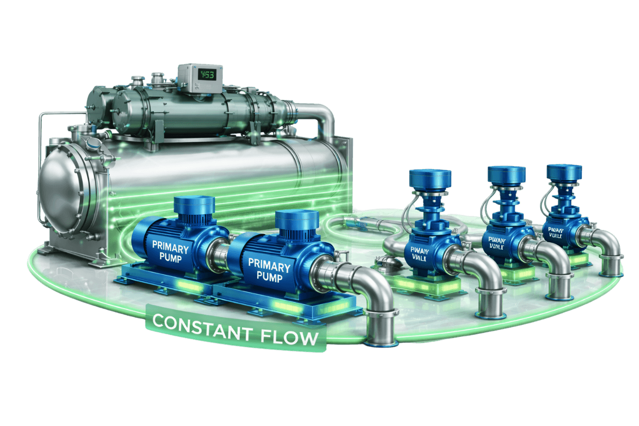
A three-way valve is only one part of a working circuit. How well it performs depends on:
- the valve's size and flow characteristic
- the actuator's signal, speed and force
- the balancing valve in the bypass leg
- the pumps and piping that keep total flow constant
- the control loop that positions the valve
Compress India engineers all of these together:
- 1. Survey and data collection: we record coil schedules, pipe sizes, pump data and existing control signals.
- 2. Hydronic design: we calculate coil flows, valve Kv, bypass balancing and pump head.
- 3. Valve and actuator selection: we specify valve type, size, port configuration, actuator signal and fail-safe needs.
- 4. Supply coordination: we manage approved makes, datasheets and delivery schedules.
- 5. Installation: we install coil hook-ups, bypass legs, balancing valves, insulation and wiring.
- 6. TAB and commissioning: we run stroke tests and signal checks, balance coils and bypasses, and tune control loops.
- 7. Lifecycle support: we provide AMC, trend reviews and upgrade planning.
What Is Constant Flow with Three-Way Valve Control?
Constant flow with three-way valve control is a hydronic control method with two parts. Constant speed chilled water pumps deliver a fixed flow, and a three-way valve at each coil decides how that flow is shared between the coil and a bypass. When the space needs more cooling, the valve sends more water through the coil; when it needs less, more water goes through the bypass. Total flow in each circuit stays essentially constant, and so does flow in the whole constant flow hydronic system.
This approach is also called a three-way valve constant flow system or a constant flow three-way valve system. It is the classic form of chilled water three-way valve control. It is also the terminal control method used in most primary constant flow systems and constant volume chilled water systems.
What Is a Three-Way Control Valve?
A three-way control valve is a valve with three ports, usually marked A, B and AB, that modulates or switches flow between two paths. In an HVAC application, one path feeds the coil, the other feeds the bypass, and the common port connects to the supply or return pipe.
An actuator moves the valve's plug, ball or rotor in response to a controller. Depending on the actuator, the valve works as a modulating chilled water valve or as an on/off 3 way chilled water valve. These valves are also called:
- 3 port valves or 3 port control valves
- 3 way regulating valves
- 3 way flow control valves or 3 port flow control valves
The term "3 way valve" also covers many devices outside HVAC. Here is how HVAC three-way control valves compare with other three-way valves people often search for:
| Valve Type | How It Works | Typical Use | Used for HVAC Coil Control? |
|---|---|---|---|
| Three-way control valve (globe, characterized ball or rotary) | An actuator modulates flow between ports A and B, with AB as the common port | Chilled water and hot water coils, heat exchangers | Yes |
| 3 way motorised valve / motorized ball valve 3 way (T-port or L-port) | A motor turns a ball or plug for on/off or modulating duty | FCUs, zone control, changeover circuits | Yes |
| 3 way solenoid valve | A solenoid moves a plunger to switch ports instantly; normally closed or normally open; direct-acting or pilot operated | Small water, air and pneumatic duties | Rarely; fast switching can cause water hammer |
| 3 way thermostatic valve / 3 way thermostatic mixing valve | A self-acting wax element moves the valve as water temperature changes, with no external power | Engine and compressor cooling, domestic hot water blending | No; used for equipment cooling and plumbing |
| 3/2, 3/3 and 4/3 way directional control valves (spool valves) | A spool shifts to direct air or oil to cylinders and actuators | Pneumatic and hydraulic machinery | No |
| Hydraulic flow and pressure control valves | Regulate oil flow or pressure, for example 3 way pressure compensated flow control valves | Hydraulic power units and machine tools | No |
A few working principles explain the differences.
3 way solenoid valves: energizing the coil pulls a plunger that switches flow between ports. A normally closed valve stays shut until powered. Pilot-operated versions use a small 3 way pilot valve to move a larger seal. A 3 way solenoid valve schematic numbers the ports 1, 2 and 3, or P, A and R in older pneumatic notation. Small 3 way water solenoid valves switch instantly, which is why they are rarely used on chilled water coils.
3 way temperature control valves: these move the plug gradually rather than snapping between ports. The movement comes either from an actuator responding to a controller, or from a thermostatic element. AMOT 3 way thermostatic control valves on engine and compressor cooling circuits are a common example of the thermostatic type.
For chilled water coils, motorized modulating valves with controlled stroke times are the right choice. They are the focus of Compress India's work.
Why Three-Way Valves Are Used in Constant Flow Systems
Three-way valves remain in use because they solve specific problems simply:
- They protect constant flow: each circuit's flow stays steady, so constant speed pumps and chillers see stable conditions.
- They prevent deadheading: even with every coil satisfied, water still has a path through the bypasses.
- They protect chillers: evaporator flow stays within limits without extra flow-control logic.
- They simplify pump control: pumps run at one duty point, with no DP sensors or VFDs.
- They give independent coil control: with balanced bypasses, each coil's temperature is controlled without disturbing flow to the others.
- They suit legacy plants: many existing plants were designed around three-way valves and still depend on them.
How Three-Way Valve Control Works in a Constant Flow System
1. Constant Speed Pumps Deliver Fixed System Flow
A constant speed chilled water pump delivers design flow to the distribution system at all times. The constant flow pumping system runs at one duty point, set during design and confirmed during balancing.
2. Temperature Sensor Measures Load Demand
A room, return air or supply air temperature sensor measures how well each coil is meeting its load. It feeds that reading to the controller.
3. Controller Modulates the Three-Way Valve
The controller compares the measured temperature with setpoint and repositions the actuator. This three-way valve temperature control opens the coil port for more cooling and the bypass port for less.
4. Water Divides Between Coil and Bypass
Water entering the circuit splits between the coil and the chilled water coil bypass according to valve position. The coil receives the flow it needs, and the rest travels through the bypass at supply temperature.
5. Total System Flow Remains Constant
Coil flow and bypass flow always add up to the circuit's design flow, so the pumps and chillers see constant chilled water flow. In short, the three-way valve keeps flow constant at every load.
Main Components of a Constant Flow Three-Way Valve System
| Component | Role in the System |
|---|---|
| Three-way control valve | Divides flow between coil and bypass |
| Actuator | Positions the valve in response to the control signal |
| Bypass line | Carries water around the coil at part load |
| Bypass balancing valve | Matches bypass resistance to the coil path |
| Circuit balancing valve | Sets design flow through the circuit |
| Isolation valves and strainer | Allow servicing and protect the valve and coil |
| P/T test points and thermometers | Allow pressure, temperature and flow checks |
| Temperature sensor and controller | Measure load and command the valve |
| Constant speed pumps | Deliver fixed system flow |
| Chillers with flow switches | Produce chilled water with proven evaporator flow |
| BMS | Provides monitoring, alarms and trends |
Types of Three-Way Control Valves
Mixing Three-Way Valves
A three-way mixing valve has two inlets (A and B) and one outlet (AB). In HVAC it is usually fitted on the return side of the coil, where it combines coil return water with bypass water. The three-way mixing valve is the most widely used type in HVAC. A 3 way mixing control valve is often the default choice for FCUs and AHUs.
Diverting Three-Way Valves
A three-way diverting valve has one inlet (AB) and two outlets (A and B). It is fitted on the supply side and splits flow between the coil and the bypass. Diverting valves have internals designed specifically for the flow split. A 3 port diverting valve or 3 way diverting control valve is common in some heating, process and cooling tower applications.
Globe-Type Three-Way Valves
A 3 way globe valve uses a plug that moves linearly between two seats. 3 way globe control valves offer precise modulation, good close-off and a wide size range, from threaded FCU valves to large flanged AHU and plant valves. In industrial plants, a 3 way control valve with pneumatic actuator is common where compressed air is available. On/off versions are switched by a 3 way pneumatic solenoid valve (a 3/2 air solenoid valve), while modulating versions use a positioner.
Characterized Ball-Type Three-Way Valves
A characterized ball valve uses a ball with a T-port or L-port bore, plus a characterizing disc that shapes its flow curve. These valves are compact, have low leakage and suit FCUs and small to medium AHUs. Motorized T-port 3 way ball valves are also popular for on/off zone control.
Rotary / Shoe-Type Three-Way Valves
A 3 way rotary valve uses a rotating shoe or sector inside a cylindrical body to blend or divert flow. Rotary valves are simple, robust and tolerant of dirt, which makes them popular for heating circuits, radiant systems and some process mixing duties. Their leakage is usually higher than that of seated valves, so they are less suited to applications that need tight shut-off.
Comparison Table – Mixing vs Diverting Three-Way Valves
| Parameter | Mixing Valve | Diverting Valve |
|---|---|---|
| Ports | Two inlets (A, B), one outlet (AB) | One inlet (AB), two outlets (A, B) |
| Position in the coil circuit | Return side | Supply side |
| Function | Combines coil and bypass flows | Splits supply flow between coil and bypass |
| Availability | Widest range of sizes and makes | Narrower range |
| Common HVAC use | FCUs, AHUs and most chilled water coils | Some heating, process and cooling tower duties |
| Key installation point | Flow must enter ports A and B | Flow must enter port AB |
Three-Way Valve Port Configuration & Flow Paths
Common Port (AB), Coil Port (A) & Bypass Port (B)
Most manufacturers mark the common port AB, the control or coil port A and the bypass port B. The two end positions work like this:
- Actuator fully open: A–AB is open and B–AB is closed, so all the water goes through the coil.
- Actuator fully closed: A–AB is closed and B–AB is open, so all the water bypasses.
Some manufacturers use different markings, so we check every datasheet before installation.
Installing Valves on Supply vs Return Side
A mixing valve belongs on the return side of the coil, and a diverting valve on the supply side. Return-side mixing valves are the most common arrangement in chilled water systems. Mixing valves are widely available, and on the return side the valve sits downstream of the coil and its strainer.
Correct Valve Orientation for Mixing & Diverting Applications
Flow direction matters. Globe plugs are designed for flow in one direction, so a mixing valve installed as a diverter, with flow entering the AB port, can chatter, bang or fail to control. Some ball-type valves accept either duty, but only when the manufacturer confirms it. We check flow arrows, port markings and actuator action on every valve.
Three-Way Valve Actuator Types
The actuator turns a 3 way modulating valve into a working 3 way automatic control valve. Because the drive is electric, these assemblies are sometimes called 3 way electric water valves.
On/Off Actuators
On/off actuators drive the valve fully open or fully closed on a thermostat signal. A 3 way motorised valve with an on/off actuator is common on FCUs and simple zone circuits.
Floating (3-Point) Actuators
Floating actuators receive separate "open" and "close" signals and hold position when neither is present. They provide modulating control from simple controllers and are widely used on FCUs and small AHUs.
Modulating Actuators (0–10V / 4–20mA)
Modulating actuators position the valve anywhere in its stroke in response to a 0–10 V, 2–10 V or 4–20 mA signal, making it a true 3 way proportional valve. Most provide position feedback, and they are the standard choice for AHUs.
Fail-Safe (Spring Return) Actuators
Fail-safe actuators use a spring or stored energy to return the valve to a defined position on power loss. Heating coils often fail open to the coil. Cooling applications fail to the coil or to bypass, depending on which position is safer for the process.
Smart Actuators with BACnet / Modbus Communication
Smart actuators connect directly to the BMS over BACnet or Modbus, receiving commands and reporting position, alarms and diagnostics. They simplify wiring and make troubleshooting much faster.
Valve Characteristics & Authority
Linear vs Equal Percentage Characteristics
A linear valve changes flow in direct proportion to stroke. An equal percentage valve changes flow by the same percentage for each step of stroke, giving small changes near closed and large changes near open. Coil output rises quickly at low flow, so the coil port (A–AB) is usually equal percentage. Many three-way valves pair it with a linear bypass port (B–AB) to keep total flow steadier.
Valve Authority in Three-Way Valve Circuits
Valve authority compares the valve's pressure drop with the pressure drop of the part of the circuit whose flow it varies, mainly the coil. A common target is around 0.5, which means sizing the valve for a pressure drop similar to the coil's. Total flow in a three-way circuit stays nearly constant, so the pressure across the circuit is stable and authority holds up better than in many two-way systems.
Flow Variation Between Coil and Bypass Paths
Unless the bypass is balanced, the coil path and bypass path have different resistances. When the bypass flows more easily, the circuit passes more water in full bypass than at full coil flow. This disturbs flows to other circuits and upsets the system balance.
Flow Increase at Mid-Stroke Valve Position
At mid-stroke, both ports are partly open and the two paths act in parallel. Total circuit flow can then rise noticeably above design, depending on the valve characteristic and how well the bypass is balanced. With equal percentage characteristics on both ports, it can instead dip below design. An equal percentage coil port, a linear bypass port and a properly balanced bypass together keep this variation small.
Three-Way Valve Applications by Equipment
Three-Way Valves for AHUs
A three-way valve for AHU cooling coils is typically a modulating globe or characterized ball valve controlling supply or return air temperature. In a constant flow system, the three-way control valve for AHU duty acts as the AHU chilled water control valve. It is sized on coil flow and pressure drop and paired with a balanced bypass.
Three-Way Valves for FCUs
A three-way valve for FCU coils is usually a compact threaded valve with an on/off, floating or modulating actuator. As the FCU chilled water control valve, it keeps each fan coil circuit at constant flow, so neighbouring FCUs are unaffected.
Three-Way Valves for Process Heat Exchangers
Three-way valves control process heat exchangers by bypassing part of the cooling water around the exchanger. Process temperatures stay steady while the supply loop sees constant flow.
Three-Way Valves for Cooling Tower Bypass
A three-way diverting valve on the condenser water line can send part of the flow around the cooling tower fill. This stops condenser water from getting too cold for the chiller in cool weather or at light load.
Three-Way Valves for Hot Water & Heating Coils
In heating systems, three-way valves control reheat coils, preheat coils and heat exchangers. Mixing arrangements also blend return water into the supply to deliver a controlled, lower flow temperature for radiant or low-temperature circuits.
End-of-Line Three-Way Valves for Minimum Flow
In variable flow systems, a few three-way valves at the ends of long runs keep a minimum flow moving. Water near remote terminals stays cold and the pumps never deadhead. They are a practical compromise, but their number should be limited, because every bypass reduces delta-T.
Benefits of Constant Flow with Three-Way Valve Control
Constant Flow Through Chillers
Chillers always see their design evaporator flow, which keeps capacity control stable and avoids low-flow trips.
Stable System Pressure
With total flow constant, system pressures hardly change as coils load and unload, so every circuit sees steady conditions.
Simple Pump Operation
Pumps run at a single duty point, with no VFDs, DP sensors or speed control loops to set up.
No Pump Deadheading
Even when every coil is satisfied, water always has a path through the bypasses, so the pumps never run against closed valves.
Lower Controls Complexity
Each valve needs only a temperature sensor and a controller or thermostat. There is no system-level pressure control to commission.
Reliable Temperature Control at Individual Coils
With balanced bypasses and stable pressure, each three-way valve controls its coil predictably. Other valves opening and closing don't disturb it.
Suitable for Small Systems & Constant Process Loads
In small plants and steady process applications, three-way valve control gives reliable results at minimal cost and complexity.
Limitations & Design Challenges
Constant Pumping Energy at All Loads
Pumps move design flow all year, even when most of it bypasses the coils. On larger systems, this is the biggest energy penalty.
Low Delta-T at Part Load
Bypass water returns at supply temperature and dilutes the coil return, so return temperature falls as load drops. Three-way valve low delta-T is built into the design.
Reduced Chiller Plant Efficiency
Lower return temperatures mean chillers deliver less cooling per litre pumped. In multi-chiller plants, this can keep extra chillers and pumps running at low load.
Bypass Balancing Problems
A bypass without a balancing valve, or with a wrong setting, overflows in full bypass and starves other circuits. Bypass balancing is essential.
Overflow at Mid-Stroke Valve Positions
Depending on valve characteristics and balancing, circuit flow can rise at mid-stroke. This adds to overflows near the pumps.
Energy Code Compliance Concerns
Energy codes generally expect larger hydronic systems with modulating valves to vary flow with load. Above certain sizes, systems with three-way valves at most terminals may not comply.
Three-Way Valve vs Two-Way Valve Control
Three-way valve vs two-way valve is the central choice in chilled water flow regulation.
| Parameter | Three-Way Valve | Two-Way Valve |
|---|---|---|
| System flow | Constant | Variable |
| Part-load pumping energy | High | Low, with VFD pumps |
| Delta-T | Falls at part load | Held closer to design |
| Pump requirement | Constant speed | Variable speed with DP control |
| Deadheading risk | None | Managed with VFDs or minimum flow provisions |
| Valve and piping cost | Higher per circuit, including bypass piping | Lower per circuit |
| Balancing | Coil and bypass balancing | Terminal balancing, or PICVs |
| Best suited for | Small constant flow systems and minimum flow points | Most modern chilled water systems |
Three-Way Valve vs Pressure Independent Control Valve (PICV)
A PICV is a two-way valve with a built-in differential pressure regulator and flow limiter. It modulates coil flow while automatically balancing itself against pressure changes, which makes it the building block of efficient variable flow systems.
| Parameter | Three-Way Valve | PICV |
|---|---|---|
| Flow type | Constant circuit flow | Variable system flow |
| Balancing | Manual, for coil and bypass | Automatic and dynamic |
| Pressure independence | No | Yes |
| Delta-T | Falls at part load | Protected |
| Components per coil | Valve, bypass line and balancing valves | A single PICV |
| Pumping energy | High | Low, with VFD pumps |
| Best suited for | Constant flow systems | Variable flow systems with many terminals |
True 3 way pressure independent control valves are uncommon. Where a PICV system needs minimum flow, a small bypass or an end-of-line valve does the job.
Constant Flow Three-Way Valve Systems vs Variable Flow Systems
The constant flow vs variable flow chilled water system decision shapes energy use for the life of the building.
| Parameter | Constant Flow with Three-Way Valves | Variable Flow System |
|---|---|---|
| Terminal valves | Three-way | Two-way or PICVs |
| Pumps | Constant speed | VFD-controlled |
| System flow | Fixed | Follows load |
| Energy at part load | High | Low |
| Delta-T | Low at part load | Close to design |
| Controls | Simple | DP control and setpoint reset |
| Capital cost | Lower | Higher |
| Best suited for | Small systems, steady loads | Most medium and large buildings |
Constant flow remains a sound choice for small, steady systems. For most medium and large buildings, variable flow pays for its extra cost through lower energy bills.
When Is Three-Way Valve Control the Right Choice?
Small Chilled Water Systems
With small pumps and only a few coils, the energy penalty is modest and the simplicity is valuable.
Single-Chiller Constant Flow Plants
A single chiller with constant speed pumps needs steady evaporator flow. Three-way valves provide it without any extra controls.
Process Cooling with Constant Loads
Where loads barely vary, three-way valves hold process temperatures precisely while the loop stays at constant flow.
Minimum Flow at End of Line
Even in variable flow systems, a few end-of-line three-way valves remain a practical way to maintain minimum circulation.
Existing Legacy Installations
Many legacy plants still run well on three-way valves. Like-for-like replacement of failed valves, rebalancing and actuator upgrades can extend their life cost-effectively.
ECBC & ASHRAE 90.1 Considerations for Constant Flow Systems
From a code perspective, the real question is not whether three-way valves are allowed, but how many and where. ECBC and ASHRAE 90.1 generally expect two things from larger chilled water systems with modulating control valves:
- flow that varies with load
- pump power that falls at part load
In practice, this shapes valve selection as follows:
- Terminal control: in larger systems, most terminals are expected to use two-way valves or PICVs.
- Minimum flow: a small number of three-way valves or bypasses to protect minimum flow is common practice, provided the overall system meets the code's variable flow provisions.
- Small systems: these may fall below code thresholds or qualify for exceptions, depending on the edition and system size.
- Renovations: major valve replacements and plant upgrades are the ideal time to bring terminal control in line with current codes.
- Green building ratings: IGBC, GRIHA and LEED projects typically benefit from keeping three-way valves to a minimum.
Compress India reviews code requirements with your MEP consultant before valve schedules are finalized.
Constant Flow with Three-Way Valve Control for HVAC
In HVAC, three-way valve bypass control remains common in small offices, showrooms, clinics, restaurants and older buildings. A constant flow HVAC system of this kind puts a cooling coil three-way valve at every AHU and FCU. The result is simple, dependable three-way valve control for chilled water distribution across the building.
Compress India supplies and installs three-way control valves with correctly balanced bypasses, matched actuators and tuned control loops. For existing buildings, we also help you decide which valves to keep, which to replace like-for-like and which to convert to two-way valves or PICVs.
Constant Flow with Three-Way Valve Control for Industrial & Process Cooling
Industrial plants use three-way valves well beyond HVAC coils: process heat exchangers, jacket cooling, moulding machine circuits and cooling tower bypass. In process plants, a 3 way temperature control valve, often a 3 way pneumatic control valve where instrument air is available, holds process temperatures steady. On engines and compressors, self-acting three way thermostatic valves regulate jacket and oil cooling without external power.
Compress India designs these circuits with robust valves, strainers suited to process water, correctly balanced bypasses and integration with process controls. Production temperatures stay stable while the cooling loop runs at constant flow.
Applications of Constant Flow Three-Way Valve Systems
Small Commercial Buildings & Offices
Three-way valves on a handful of AHUs and FCUs give small offices simple, dependable temperature control from a single chiller.
Showrooms & Retail Outlets
Showroom AHUs with three-way valves hold comfortable display-area temperatures through long trading hours, while the chiller sees steady flow.
Small Hospitals & Clinics
Clinics and nursing homes value predictable control. Three-way valves with fail-safe actuators move critical coils to a safe default position during power interruptions.
Hotels & Restaurants
Guest room FCUs with on/off three-way valves, combined with modulating valves on banquet and kitchen AHUs, keep a small hotel plant simple to run.
Manufacturing & Process Cooling
Process heat exchangers and machine cooling circuits use three-way valves to hold temperatures while the loop stays at constant flow.
Plastic & Injection Moulding Units
Mould temperature control depends on steady cooling. Three-way valves on mould circuits and hydraulic oil coolers bypass excess water and keep temperatures stable from cycle to cycle.
Laboratories
Laboratory cooling loops use small three-way valves to hold instrument temperatures within tight limits, independent of other users on the loop.
Legacy Buildings with Existing Constant Flow Plants
Older buildings often need failed three-way valves replaced, actuators upgraded and bypasses rebalanced. We handle all three, and plan conversions when the savings justify them.
System Design & Sizing
Coil Flow Calculation
Coil flow comes from coil load and design delta-T. Each TR of chilled water load needs about 2.4 GPM at a 10 °F delta-T, or roughly 0.55 m³/h at 5.5 °C. On that basis:
- a 50 TR AHU needs about 120 GPM (27 m³/h)
- a 1.5 TR fan coil needs about 0.8 m³/h
Three-Way Valve Sizing (Cv / Kv Calculation)
Valves are sized on flow and pressure drop, not pipe size:
Kv = Flow (m³/h) ÷ √ΔP (bar) Cv = Flow (GPM) ÷ √ΔP (psi), where Cv ≈ 1.156 × Kv
Take the 50 TR AHU above, carrying 27.3 m³/h, with a coil pressure drop of 0.4 bar. The target Kv is about 43. A Kvs 40 valve gives roughly 0.47 bar at design flow, equivalent to a Cv of about 46. The selected valve is often one or two sizes smaller than the pipe.
Bypass Balancing Valve Sizing
At design flow, the bypass balancing valve must create the same pressure drop as the coil path it replaces, meaning the coil plus its connecting pipework. We select a valve that reaches this pressure drop at a mid-range setting, often the same size as, or one size smaller than, the coil connection. Specifications sometimes call for a "3 way balancing valve"; in practice, a three-way circuit is balanced with one balancing valve in the circuit and a second in the bypass.
Pump Head Calculation
Pump head is the sum of losses along the index path:
- the chiller evaporator
- supply and return piping
- the index circuit's coil, three-way valve and balancing valve
- strainers and fittings
Circuit flow is constant, so the calculation is straightforward, but the margins must stay realistic.
Chilled Water Delta-T Selection
Design delta-T sets the flow. A higher delta-T means less flow, smaller valves and lower pump power, provided the coils are selected to match. In three-way systems, design delta-T is achieved only at full load.
Pipe Sizing for Constant Flow Circuits
Each circuit is sized for its design flow, which is also its operating flow for every hour. Moderate velocities keep noise and erosion low at the valve and bypass, and consistent sizing makes balancing easier.
Three-Way Valve Selection Criteria
Valve Size & Flow Coefficient
Select the valve's Kvs or Cv to meet the target pressure drop at design flow. Oversized valves control poorly near closed, while undersized valves starve the coil and add pump head.
Pressure Rating & Close-Off Pressure
The body rating, for example PN16, must suit system pressure, including static head in tall buildings. The close-off pressure is the differential pressure the actuator can shut against, and it must exceed the highest pressure difference the valve will see.
Body Material & Connection Type (Threaded / Flanged)
Small valves usually have bronze or brass bodies with threaded ends. Larger valves use cast iron or ductile iron bodies with flanges. The material must suit the water quality and temperature.
Actuator Torque, Signal & Speed
Actuator force or torque must exceed what the valve needs at close-off, and the signal type must match the controller. Stroke time must suit the control loop: fast enough for AHU response, but not so fast that it causes hunting.
Leakage Class
Leakage is the flow that passes a closed port. Datasheets often specify leakage separately for the control port and the bypass port. Industrial valves are rated to classes such as ANSI/FCI 70-2 Class IV or Class VI. Lower leakage improves control at light load.
Common Three-Way Valve Brands Used in HVAC Projects
Several established manufacturers supply three-way control valves to Indian HVAC projects. Compress India works with the make approved by your consultant, or helps you compare options on performance, availability and cost.
Belimo Three-Way Valves
Belimo offers characterized control valves in 2-way and 3-way versions, globe valves for larger duties, and a wide range of actuators: on/off, floating, modulating, spring-return and communicative. A Belimo 3 way control valve is often chosen for its compact characterized ball design and low leakage.
Siemens Three-Way Valves
Siemens offers three-port globe and ball valves in its Acvatix range, in threaded and flanged versions. They are paired with electromotive actuators for modulating and on/off control.
Honeywell Three-Way Valves
Honeywell's range includes 3-way motorised zone valves widely used on FCUs, plus 3-way globe valves and actuators for AHUs and plant duties. A Honeywell 3 way motorised valve is a familiar sight in many hotel and office FCU installations.
Danfoss Three-Way Valves
Danfoss supplies 3-way seated valves in threaded and flanged versions for heating, cooling and district energy applications. They are used with its AMV (3-point) and AME (modulating) actuator ranges.
Johnson Controls Three-Way Valves
Johnson Controls offers ball and globe control valves in 2-way and 3-way versions. Their electric actuators integrate with Johnson Controls' own BMS and with third-party platforms.
Other Three-Way Valve Brands
Other makes used on HVAC projects include Schneider Electric, Sauter, ESBE (known for rotary mixing valves) and Indian manufacturers. Whatever the brand, we check Kvs, characteristics, close-off pressure, leakage and actuator compatibility against your project.
Piping & Installation Arrangement at Coils
Typical Three-Way Valve Coil Connection Assembly
A typical return-side mixing arrangement is laid out as follows:
- Supply side: an isolation valve and strainer ahead of the coil inlet.
- Return side: the coil outlet with a P/T point, then the three-way mixing valve. Port A comes from the coil, port B from the bypass, and port AB goes to the return. After the valve come a circuit balancing valve and an isolation valve.
- Bypass: the bypass tees off the supply line after the strainer and connects to port B through its own balancing valve.
This complete three-way valve chilled water bypass arrangement keeps every circuit at constant flow.
Bypass Line with Balancing Valve
The bypass line carries water around the coil as the valve modulates. A balancing valve in the line, set to the coil's pressure drop, keeps circuit flow the same at full coil and full bypass. Every three-way valve with bypass needs this balancing valve, and every three-way control valve with bypass should be commissioned with it set.
Isolation Valves & Strainers
Isolation valves on the supply and return let the valve, coil or strainer be serviced without draining the system. A strainer upstream protects the valve seats and coil tubes.
P/T Test Points & Thermometers
Test points allow pressure and flow checks across the coil and valve. Thermometers or temperature sensors on supply and return show coil performance at a glance.
Insulation of Valves and Fittings
Valve bodies, bypass lines and fittings all carry chilled water, so they must be insulated against condensation. Removable insulation jackets keep valves accessible, while actuators stay uninsulated.
Water Balancing in Three-Way Valve Systems
Balancing the Coil Path
With the valve fully open to the coil (A–AB), the circuit balancing valve is set to deliver design flow through the coil.
Balancing the Bypass Path
With the valve in full bypass (B–AB), the bypass balancing valve is set to deliver the same design flow. Both end positions then give equal circuit flow.
Proportional Balancing Method
Once each circuit is balanced internally, circuits are balanced against each other across branches and risers. The work starts from the index circuit, so every circuit reaches design flow with the fewest adjustments.
Flow Measurement & Verification
Flows are measured through the balancing valve test points with a balancing instrument, in both full-coil and full-bypass positions. The readings are recorded in the TAB report.
Controls, Automation & BMS Integration
Room / Return Air Temperature Control Loop
FCU thermostats and AHU controllers compare room or return air temperature with setpoint and drive the three-way valve to match.
AHU Supply Air Temperature Control
A supply air temperature loop modulates the valve for precise discharge temperatures. The supply air setpoint is often reset from room or return air temperature.
PID Loop Tuning for Three-Way Valves
PI control is usually enough, and derivative action rarely helps on water valves. Gains are matched to actuator stroke time and coil response. A deadband stops constant small movements that wear actuators.
Valve Position Feedback to BMS
Position feedback shows whether each valve is actually responding. It reveals stuck valves, valves that sit at full coil (a sign of undersized coils) and circuits that rarely leave bypass (a sign of oversized coils).
Chiller–Pump Interlocking
Pumps start first and prove flow before a chiller starts, and they run on after the chiller stops. Three-way valves guarantee a flow path at all times, which keeps these interlocks simple.
Energy Efficiency & Power Consumption
Pumping Energy Calculation
Pump power is estimated as:
Pump power (kW) = Flow (m³/h) × Head (m) ÷ (367 × combined pump-motor efficiency)
Take a 150 TR plant circulating 81.8 m³/h at 28 m head with 68% combined efficiency. The pumps draw about 9.2 kW. Running 3,650 hours a year, that is roughly 33,500 kWh, whatever the load. In this example, every 10% cut in average pump power saves about 3,350 kWh a year.
Energy Losses from Bypass Flow
Bypass flow wastes energy in three ways:
- the pumps move water that does no cooling
- return temperature falls, so chillers run less efficiently or more chillers run
- bypassed water picks up heat along long pipe runs
At light load, most of the pumped water may pass through bypasses rather than coils.
Energy Improvement Opportunities
- Balance every bypass so no circuit overflows
- Trim oversized pump impellers instead of throttling
- Replace leaking valves that pass water through closed ports
- Retune control loops to stop hunting
- Convert most three-way valves to two-way valves or PICVs with VFD pumps
- Keep three-way valves only where minimum flow is needed
Installation of Three-Way Valve Control Systems
Compress India installs three-way valve systems in a controlled sequence:
- 1. Submittals: we get the valve schedule approved, covering Kvs, characteristics, actuators and fail-safe requirements.
- 2. Port and flow checks: we confirm port markings and flow arrows before fitting any valve.
- 3. Coil hook-ups: we install coil connection assemblies with bypass lines and balancing valves.
- 4. Valve support: we support valves independently so they don't stress the coil connections.
- 5. Actuator mounting: we mount actuators with clearance for removal and manual override.
- 6. Wiring: we terminate and label power, control and feedback wiring.
- 7. Testing and insulation: we pressure test, flush and then insulate.
- 8. BMS connection: we map and test points from the controller.
Testing, Balancing & Commissioning (TAB)
Valve Stroke & Actuator Testing
Each actuator is driven through its full stroke to confirm smooth movement, correct end positions, manual override and fail-safe action.
Control Signal Verification
We check signal type, range and direction at every valve, confirming that an increasing call for cooling opens the coil port. Feedback signals are checked against actual position.
Coil & Bypass Flow Balancing
Coil and bypass paths are balanced to equal design flow, then circuits are balanced across the system. The results are recorded in the TAB report.
Temperature Control Performance Testing
With the system running, we test each loop's response to setpoint changes. Coils must reach setpoint without hunting or overshoot, and final tuning values are documented.
Maintenance & AMC for Three-Way Valve Systems
Three-way valves are robust, but neglect shows up as leakage, sticking and drift. Compress India's AMC for three-way valve systems typically includes:
- Valve exercising to prevent sticking in rarely used positions
- Actuator checks for stroke, response, feedback and fail-safe operation
- Leakage checks through closed ports, using temperature and pressure readings
- Bypass and circuit balancing checks, with resetting where needed
- Strainer cleaning at coils and plant
- Control loop reviews using BMS trends
- Insulation inspection around valves and bypass lines
- Water treatment coordination to limit scale on valve seats
AMC plans can be structured as comprehensive or non-comprehensive.
Common Problems & Troubleshooting
Valve Installed in Wrong Orientation
Swapped ports or reversed flow cause reversed control action, noise or chatter. The valve must be re-piped to match its port markings and flow arrows, or its actuator action corrected where the design allows.
Valve Sticking or Seizing
Scale, debris or long periods in one position can seize the plug or ball. Cleaning, exercising the valve or replacing internals restores movement, and good water treatment prevents recurrence.
Internal Leakage Through Bypass Port
Worn seats let water pass a closed port. Leakage through the coil port overcools the space, while leakage through the bypass reduces cooling at full demand. Seat replacement or a new valve fixes it.
Actuator Failure or Incorrect Control Signal
Typical causes are power loss, wiring faults, a mismatched signal range (0–10 V against 2–10 V), reversed action or a failed motor. Checking the signal, testing the actuator and correcting the configuration resolve most cases.
Temperature Hunting at Coils
Hunting comes from oversized valves, low authority, aggressive tuning or a stroke time that doesn't suit the loop. Correct valve sizing, retuning and deadband settings stabilize control.
Unbalanced Bypass Flow
A missing or misset bypass balancing valve lets circuits overflow in bypass mode and starve others. Rebalancing both paths restores constant circuit flow.
Low Delta-T & Chiller Short Cycling
Low return temperatures at light load can make chillers unload and cycle frequently, especially in systems with little water volume. Balancing bypasses, reviewing setpoints, adding buffer volume where needed, or converting to variable flow reduces cycling.
Retrofitting & Upgrading Three-Way Valve Systems
A three-way valve system that wastes energy or suffers from low delta-T can be upgraded in stages without replacing the plant.
Replacing Three-Way Valves with Two-Way Valves
Each three-way valve is swapped for a two-way valve and its bypass leg is removed or capped. The system becomes variable flow, so the plant needs pump speed control and minimum flow protection.
Replacing Three-Way Valves with PICVs
Replacing three-way valves with PICVs adds automatic balancing and delta-T protection in a single step. It is often the best option for buildings with many terminals or frequent tenant changes.
Converting Constant Flow to Variable Flow
Beyond the valves, conversion needs VFD pumps, a differential pressure control strategy, and a minimum flow bypass or variable primary controls to protect chillers. We design the whole conversion, not just the valve swap.
Adding VFDs & DP Control After Valve Retrofit
Once two-way valves or PICVs are installed, VFDs and a remote DP sensor let pump speed follow demand. This is where most of the pumping savings are realized.
Retaining End-of-Line Three-Way Valves for Minimum Flow
A few three-way valves are often kept at the ends of long runs to maintain minimum circulation. The number is kept as low as possible, and their bypasses are balanced to limit the effect on delta-T.
Actuator Upgrades & BMS Integration
Where valves are in good condition but actuators are failing or basic, upgrading to modulating or smart actuators improves control. BMS integration adds position feedback, alarms and remote diagnostics.
Still running a building full of three-way valves? Ask Compress India for a valve and energy assessment.
Three-Way Valve System Cost in India
The cost of a three-way valve control system depends on the number and size of valves, valve and actuator types, balancing requirements and controls scope. A small office with a few AHU valves is a very different project from a hotel with hundreds of FCU valves and full BMS integration.
Compress India provides itemized proposals that separate valve supply, installation, balancing and controls. For existing systems, we also compare like-for-like replacement with conversion to two-way valves or PICVs.
Three-Way Valve Price Factors
3 way control valve price varies with:
- Valve size and Kvs, from small FCU valves to large flanged AHU valves
- Valve type: globe, characterized ball or rotary
- Body material, pressure rating and connection type
- Actuator: on/off, floating, modulating, fail-safe or smart
- Leakage class and close-off rating
- Make and country of origin
- Quantity and delivery timelines
A 3 way solenoid valve price is usually lower than that of a modulating control valve with actuator, but the two are different devices. Solenoid valves are not a substitute for coil control valves.
Factors Affecting Total Project Cost
- Number of AHUs, FCUs and heat exchangers
- New installation versus replacement of existing valves
- Bypass piping and balancing valves
- Isolation valves, strainers and test points
- Insulation and access requirements
- Actuator wiring and BMS integration
- Testing, balancing and commissioning scope
- Shutdown windows, night work and site access
- AMC requirements
Information Required for a Quotation
To prepare an accurate proposal, please share:
- Terminal unit schedule: AHUs, FCUs and heat exchangers with capacities, flows and coil pressure drops
- Pipe sizes at each coil connection
- Chilled water schematic or piping layout
- Pump and chiller details
- Actuator requirements: on/off, floating, modulating, fail-safe or BACnet/Modbus
- Controller or BMS make and signal types
- Approved or preferred valve makes
- For existing systems: current valve types, problems observed and photographs
- Project timeline and working-hour restrictions
Missing some information? Our engineers can gather it during a site visit.
Three-Way Valve Supplier & Installation Contractor in Mumbai
Looking for a three-way valve supplier and installation contractor in Mumbai? Compress India combines valve supply with hydronic engineering and site execution. Every valve is sized, installed, balanced and commissioned by one accountable team.
Mumbai's older commercial buildings, hotels and hospitals contain large numbers of three-way valves, many with worn seats, failed actuators or disturbed bypass balancing. We replace valves like-for-like where that makes sense, and plan conversions to two-way valves or PICVs where the savings justify it. For new small plants, we deliver correctly sized three-way circuits from day one.
We work across Mumbai, including Fort, Mahalaxmi, Parel, Wadala, Santacruz, Vile Parle, Andheri East, Marol, Goregaon and Mulund.
Book a site visit with Compress India for three-way valve supply, replacement or upgrade.
Hydronic Valve Solutions in Mumbai, Navi Mumbai, Thane & Maharashtra
Compress India supports hydronic valve projects across Mumbai and the wider region:
- Navi Mumbai: Vashi, Sanpada, Turbhe, Rabale, Mahape and Taloja
- Thane: Wagle Estate, Naupada, Majiwada and Ghodbunder Road
- Wider Maharashtra: Bhiwandi, Ambernath, Badlapur, Pune, Chakan, Nashik, Nagpur and Chhatrapati Sambhajinagar
Our services include:
- Three-way valve supply: globe, characterized ball and rotary valves with matched actuators
- Valve replacement: like-for-like replacement of failed three-way valves and actuators
- Balancing and TAB: coil and bypass balancing for constant flow systems
- Process cooling valves: three-way valves for heat exchangers, moulding machines and cooling tower bypass
- Conversions: two-way valve and PICV upgrades with VFD pumps and DP control
- AMC: valve exercising, actuator checks and balancing reviews
Constant Flow Three-Way Valve Solutions Across India
Beyond Maharashtra, Compress India supports three-way valve projects across India. These include commercial centres such as Delhi NCR, Bengaluru, Hyderabad, Chennai and Kolkata, and industrial hubs such as Ahmedabad, Surat, Vadodara, Coimbatore and Hosur. Our valve packages come with sizing data, port orientation details and balancing settings, so site teams can install and commission them correctly.
Every project follows the same sizing checks, installation standards and TAB procedures, wherever it is located.
Why Choose Compress India for Three-Way Valve Control Systems?
Hydronic Design & Balancing Expertise
We size valves on real coil data and balance every coil and bypass, so each circuit delivers its design flow.
Valve & Actuator Selection Support
From valve type and Kvs to actuator signal, speed and fail-safe action, we specify complete valve assemblies that suit your controls.
Complete Chiller Plant Integration
Valves, pumps and chillers are designed to work together, with proper interlocks and minimum flow protection.
Controls & BMS Integration
We connect actuators and feedback signals to your controllers and BMS, and tune every loop for stable temperatures.
Installation & Commissioning
Our team installs valves in the correct orientation, balances both paths and tests every loop before handover.
Retrofit & Energy Optimization
We identify which three-way valves to keep, replace or convert, and deliver upgrades in phases with minimal disruption.
AMC & Lifecycle Support
Valve exercising, actuator care, balancing checks and trend reviews keep your system reliable for years.
How to Choose Between Three-Way Valves, Two-Way Valves & PICVs
Choosing a control valve, 3 way or 2 way, is really a choice about how the whole system should behave:
| Situation | Best Choice |
|---|---|
| Small constant flow plant with constant speed pumps | Three-way valves |
| End of long runs in a variable flow system | A few three-way valves or a minimum flow bypass |
| Variable flow system with VFD pumps and good balancing | Two-way valves |
| Many terminals, tenant changes or balancing problems | PICVs |
| Process heat exchangers on a constant flow loop | Three-way valves |
| Existing three-way system with delta-T problems | Conversion to two-way valves or PICVs |
Not sure which fits your building? A site review will show the right mix of valves, pumps and controls, along with the expected savings.
Get a Constant Flow Three-Way Valve Solution from Compress India
Whether you need new three-way valves, replacement of failed ones or a planned move to variable flow, Compress India delivers it with one accountable team.
Connect with Our HVAC Execution Team
Call our team or send an enquiry through this page with your terminal unit schedule and valve details. Our engineers will review your system and recommend a site visit where needed. You will then receive a clear proposal covering valves, installation, balancing and commissioning.
Related Systems Types & Components
Explore our comprehensive range of hydronic system configurations and components designed for efficient water distribution.
Primary Constant Flow Systems
Learn More
Decoupled Constant Primary Systems
Learn More
Boiler-Based Constant Flow Heating Systems
Learn More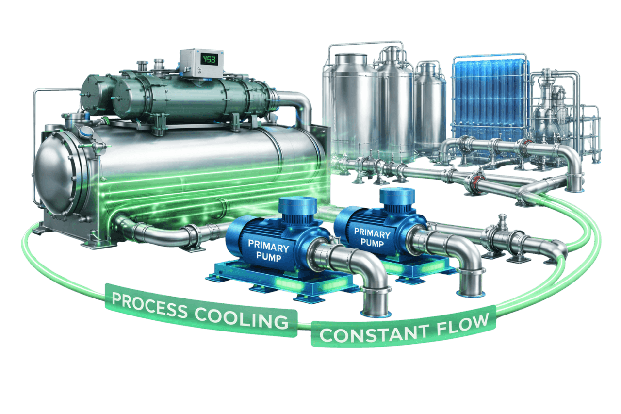
Process Cooling Constant Flow Loops
Learn MoreFrequently Asked Questions
Q1. What is constant flow with three-way valve control?
It is a hydronic control method in which constant speed pumps deliver a fixed flow. Each coil's three-way valve splits that flow between the coil and a bypass. Coil output varies with demand while total flow stays constant.
Q2. How does a three-way control valve work?
An actuator moves the valve's plug or ball between two paths: A–AB to the coil and B–AB to the bypass. Opening one path closes the other, so the circuit's total flow stays roughly the same while the coil's share changes.
Q3. What is the difference between mixing and diverting three-way valves?
A mixing valve has two inlets and one outlet and usually sits on the return side of the coil. A diverting valve has one inlet and two outlets and sits on the supply side. Each must be installed with flow in the direction it was designed for.
Q4. Why does flow remain constant in a three-way valve system?
Coil flow and bypass flow always add up to the circuit's design flow. With the bypass balanced to match the coil's resistance, the circuit presents nearly the same resistance at every valve position, so the pumps see constant flow.
Q5. Should a three-way valve be installed on the supply or return side?
Mixing valves go on the return side and diverting valves on the supply side. Return-side mixing valves are the most common arrangement in chilled water systems. Always follow the port markings and flow arrows.
Q6. Why is a balancing valve required on the bypass line?
The bypass usually has much less resistance than the coil. Without a balancing valve, the circuit overflows when the valve moves to bypass and starves other circuits. The balancing valve makes the bypass match the coil's pressure drop.
Q7. What is the difference between a three-way valve and a two-way valve?
A three-way valve keeps circuit flow constant by bypassing water around the coil. A two-way valve simply throttles flow, so system flow varies with load. Two-way valves, combined with VFD pumps, use far less pumping energy.
Q8. What is the difference between a three-way valve and a PICV?
A three-way valve diverts water around the coil and needs manual balancing. A PICV is a two-way valve with a built-in pressure regulator and flow limiter. It balances automatically and supports variable flow with high delta-T.
Q9. Why do three-way valve systems cause low delta-T?
At part load, bypassed water returns at supply temperature and mixes with coil return water. This lowers the return temperature, so delta-T shrinks as load falls.
Q10. Are three-way valves still used in modern HVAC systems?
Yes, but mainly in these situations:
- small constant flow systems
- process cooling
- cooling tower bypass
- end-of-line minimum flow
- legacy plants
Most new medium and large systems use two-way valves or PICVs.
Q11. What are end-of-line three-way valves?
They are a few three-way valves at the ends of long runs in variable flow systems. They keep a minimum flow circulating so water near remote terminals stays cold and the pumps never deadhead.
Q12. How is a three-way valve sized?
By flow and pressure drop, using Kv = Flow (m³/h) ÷ √ΔP (bar) or Cv = GPM ÷ √ΔP (psi). A common target is a valve pressure drop similar to the coil's. The chosen valve is often smaller than the pipe size.
Q13. What actuators are used with three-way valves?
The options are on/off, floating (3-point), modulating (0–10 V, 2–10 V or 4–20 mA), fail-safe spring-return and smart BACnet/Modbus actuators. The right one depends on the controller, control precision and fail-safe needs.
Q14. Can three-way valves be used for cooling tower bypass?
Yes. A three-way diverting valve on the condenser water line bypasses part of the flow around the tower fill. This keeps condenser water from getting too cold for the chiller in cool weather or at light load.
Q15. How much energy is wasted in constant flow three-way valve systems?
The pumps draw full power at every load, and at light load most of the water may pass through bypasses. Converting to variable flow often cuts pumping energy by 30–50% or more, depending on the load profile, and improved delta-T adds chiller savings on top.
Q16. Can three-way valves be replaced with two-way valves or PICVs?
Yes. The bypass legs are removed or capped, and the plant is upgraded with VFD pumps, DP control and chiller minimum flow protection. A few end-of-line three-way valves are often retained.
Q17. What are common problems with three-way valves?
The most common are:
- wrong orientation
- sticking or seizing
- internal leakage
- actuator or signal faults
- temperature hunting
- unbalanced bypasses
- low delta-T with chiller short cycling
Q18. What maintenance do three-way valves require?
They need:
- regular valve exercising
- actuator checks
- leakage and balancing checks
- strainer cleaning
- control loop reviews
- good water treatment to protect valve seats
Q19. What is the price of a three-way valve in India?
Three-way valve price depends on size, Kvs, valve type, body material, actuator, leakage class, make and quantity. A small on/off FCU valve costs far less than a large flanged modulating AHU valve. Compress India quotes against your actual valve schedule.
Q20. What information is needed for a three-way valve system quotation?
We need:
- the terminal unit schedule with flows and coil pressure drops
- pipe sizes and the chilled water schematic
- pump and chiller details
- actuator and BMS requirements
- approved makes
- for existing systems, current valve details and photographs
Q21. Does Compress India supply and install three-way valve control systems?
Yes. Compress India provides complete three-way valve solutions across Mumbai, Maharashtra and India:
- valve sizing and supply
- actuators and coil connection assemblies
- installation, balancing and commissioning
- BMS integration
- upgrades to two-way valves or PICVs
- AMC