Process Cooling Constant Flow Loops
(Design, Installation, Commissioning, Retrofit & Lifecycle Support for Industrial Process Cooling Systems)
Process Cooling Constant Flow Loops – Industrial Cooling Engineering & Execution
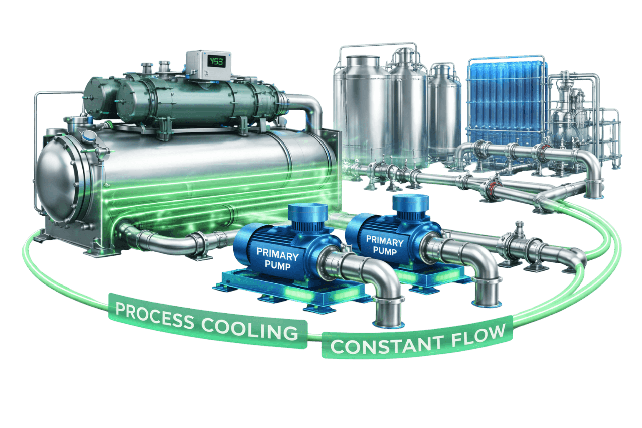
In manufacturing, cooling is part of the process. When a mould runs warm, cycle times stretch. When a laser loses flow, it trips. When a reactor jacket can't hold temperature, a batch is at risk. Process cooling constant flow loops prevent all three by delivering a steady, predictable flow of cooling water at the right temperature to every machine, every shift.
Compress India designs, installs, commissions and maintains constant flow process cooling systems for plastics, pharma, chemical, food, dairy, engineering and electronics plants across India. Each system is built as one package:
- process chillers or cooling towers
- buffer tanks and process pumps
- manifolds, piping and water treatment
- PLC-based controls
Your production team gets cooling it can rely on.
What we deliver:
- Process heat load assessment and industrial process cooling system design
- Chiller, cooling tower, pump, buffer tank and heat exchanger selection
- Process cooling piping systems, machine manifolds, hoses and insulation
- Water treatment, filtration and machine protection instrumentation
- PLC, SCADA and BMS integration with remote monitoring
- Commissioning, AMC, retrofits and capacity expansion
Share your machine list and cooling requirements with Compress India for a process cooling proposal.
Process cooling is unforgiving. A loop that is slightly undersized, poorly balanced or badly filtered shows up quickly as rejected parts, slower cycles or unplanned downtime. Getting it right means engineering the whole system around your machines, not just selecting a chiller.
Compress India delivers every industrial process cooling loop as a complete engineering and execution project:
- 1. Process audit: we record machine-by-machine heat loads, flow and temperature requirements, and operating schedules.
- 2. System design: we select the loop type, supply temperatures, chiller and tank capacity, pump duty and pipe sizes.
- 3. Equipment selection: we choose chillers, towers, pumps, tanks, heat exchangers, filters and instruments.
- 4. Installation: we install the plant room equipment, headers, machine manifolds, piping, insulation, electrical works and controls.
- 5. Testing and commissioning: we pressure test, flush, balance flows, run temperature stability tests and check every alarm.
- 6. Lifecycle support: we provide water treatment monitoring, AMC, trend reviews and upgrades as your production grows.
What Is a Process Cooling Constant Flow Loop?
A process cooling constant flow loop is a recirculating process cooling system in which constant speed pumps deliver a fixed flow of cooling water to production machines and process equipment. The water picks up heat at each machine and returns to a chiller, cooling tower or heat exchanger to be cooled again. Every machine receives its design flow whenever it runs.
It is also called a constant flow process cooling system, constant flow cooling water loop or constant flow process water loop. The approach is the backbone of manufacturing process cooling in India. It is simple, robust, and matched to machines designed for a specific cooling water flow rate.
What Is Industrial Process Cooling?
Industrial process cooling removes heat generated by manufacturing processes and equipment: moulds, extruders, reactors, hydraulic systems, compressors, lasers, welders and product heat exchangers. An industrial cooling water system carries that heat away and rejects it through a chiller, cooling tower or dry cooler. Process cooling heat rejection is what keeps machines within their operating limits and products within specification.
Process cooling vs HVAC cooling is an important distinction, because the design priorities are very different:
| Parameter | Process Cooling | HVAC Cooling |
|---|---|---|
| Purpose | Removes heat from machines and products | Keeps people comfortable |
| Load pattern | Often steady, frequently 24/7 | Varies with weather and occupancy |
| Temperature tolerance | Often tight and product-critical | Wider comfort band |
| Supply temperature | Wide range, from glycol below 0 °C to tower water around 30 °C | Typically around 6–8 °C chilled water |
| Flow requirement | Fixed flow per machine | Usually varies with load |
| Water quality needs | Strict, because machine channels are small | Standard closed-loop treatment |
| Cost of failure | Production loss and rejected product | Comfort complaints |
Why Constant Flow Is Used in Process Cooling Applications
Constant flow is the natural fit for most production equipment:
- Machines are designed for fixed flow: chillers, lasers, induction heaters and moulds specify a cooling water flow rate, and many shut down on low flow.
- Heat transfer depends on velocity: mould channels and heat exchangers need enough flow for turbulent, efficient heat transfer.
- Product quality depends on stability: steady flow keeps part temperatures, cycle times and product quality consistent.
- Loads are often steady: in continuous processes, flow varies little, so constant flow matches demand.
- Chillers stay protected: evaporator flow stays constant, avoiding low-flow trips and freezing risk.
- Operation stays simple: production teams get a system that is easy to understand, maintain and troubleshoot.
How a Process Cooling Constant Flow Loop Works
1. Chilled Water Production in the Process Chiller
The process chiller cools water, or a water-glycol mix, to the required supply temperature. The chiller loop pump keeps a constant flow through its evaporator, and the chiller's controls stage or unload compressors to hold the setpoint.
2. Buffer Tank / Reservoir Stabilizing Loop Temperature
Chilled water flows into an insulated buffer tank or reservoir. The tank's thermal mass smooths out load swings, prevents chiller short cycling and separates the chiller loop from the process loop.
3. Constant Speed Process Pumps Delivering Fixed Flow
Constant speed process pumps draw chilled water from the tank and deliver it through supply headers and manifolds to each machine. Every process cooling water pump runs at a fixed duty point, sized for the full connected flow.
4. Heat Removal at Process Equipment
At each machine, cooling water flows through moulds, jackets, oil coolers or heat exchangers, absorbing heat. Flow is set by manifold valves and balancing devices, so each machine receives its design flow.
5. Return Water Flowing Back to the Tank / Chiller
Warmed water returns through the return manifold to the tank. The chiller loop then cools it again, and the process cooling circulation system keeps the cycle going around the clock.
Main Components of a Process Cooling Constant Flow Loop
| Component | Role in the System |
|---|---|
| Process chillers | Produce chilled water or glycol at the required temperature |
| Cooling tower, closed-circuit tower or dry cooler | Rejects heat for higher-temperature loads or chiller condensers |
| Buffer tank / reservoir | Adds thermal mass and decouples the chiller and process loops |
| Chiller loop pumps | Maintain constant flow through the chillers |
| Process pumps with standby | Deliver fixed flow to machines |
| Plate heat exchangers | Isolate clean process loops from plant or tower water |
| Supply and return headers and manifolds | Distribute flow to individual machines |
| Valves, strainers and check valves | Allow isolation, protect equipment and prevent backflow |
| Pressure relief bypass valve | Protects pumps and holds flow when machines are valved off |
| Flow switches and flow meters | Confirm flow at chillers and critical machines |
| Temperature and pressure sensors | Monitor supply, return and machine conditions |
| Tank level switches | Protect pumps and control make-up water |
| Filters and water treatment equipment | Keep water clean and control scale and corrosion |
| PLC control panel | Handles interlocks, sequencing, alarms and SCADA or BMS integration |
Types of Process Cooling Constant Flow Loops
Closed-Loop Process Cooling Systems
In a closed loop process cooling system, the water circulates in a sealed, pressurized circuit with an expansion tank and is never exposed to air. A closed loop cooling water system stays clean, needs less treatment and protects small machine channels from fouling.
Open-Loop Process Cooling Systems
Open loops expose the water to air, either through a cooling tower or an open tank. They are simple and inexpensive, but the water picks up dust, oxygen and biological growth. Open loops therefore need stronger filtration and treatment to protect machines.
Tank-Based Two-Pump (Chiller Loop + Process Loop) Systems
In the most common industrial arrangement, a chiller loop pump circulates water between the tank and the chiller, while a separate process pump supplies the machines from the same tank. Partitioned tanks with separate warm and cold compartments keep return water away from the chilled supply. The tank decouples the two loops, so each pump runs at its own constant flow.
Direct Chiller-to-Process Loops
A single pump circulates water from the chiller directly to the machines and back. This saves space and cost, but the system has less water volume. Designers usually add a buffer tank, bypass or minimum flow protection to prevent short cycling and low-flow trips.
Heat Exchanger–Isolated Process Loops
A plate heat exchanger separates the process loop from plant chilled water or cooling tower water. Plate heat exchanger process cooling keeps sensitive equipment on clean, treated or deionized water, while the plant side can use tower water or a central chiller.
Comparison Table – Open vs Closed Process Cooling Loops
Open loop vs closed loop process cooling compares as follows:
| Parameter | Open Loop | Closed Loop |
|---|---|---|
| Exposure to air | Yes, through a tower or open tank | No; sealed and pressurized |
| Water quality | Harder to control | Clean and stable |
| Treatment effort | High: biocides, scale control, filtration | Lower: inhibitors and occasional filtration |
| Fouling risk in machines | Higher | Lower |
| Water losses | Evaporation, drift and blowdown | Minimal |
| Pump head | Includes static lift in open circuits | Static head balances out |
| Capital cost | Lower | Higher, with heat exchanger or closed-circuit tower |
| Best suited for | Tolerant equipment, large low-grade loads | Precision machines, lasers, moulds, pharma |
Process Cooling Loop Configurations
Single Chiller with Single Process Pump
One chiller, one tank and one process pump serve a small machine group. This setup is simple and economical, but offers no redundancy.
Multiple Chillers with Common Process Header
Several chillers cool a common tank or header, and process pumps draw from it. Chillers stage with load, and the loss of one chiller doesn't stop production.
Dedicated Loops for Individual Machines
Critical or unusual machines, such as lasers, induction furnaces or machines needing a different temperature, get their own dedicated loop, often with a heat exchanger or temperature control unit.
Supply & Return Manifold Distribution
Supply and return manifolds at each machine group distribute flow through individual valves, hoses and couplings. Each machine can be isolated for mould changes or maintenance without disturbing the others.
Duty–Standby Process Pump Arrangement
Every critical loop has a duty and a standby cooling water circulation pump. The standby starts automatically on pump failure or low pressure, so production continues.
Role of Buffer Tanks & Reservoirs
Thermal Mass & Temperature Stability
Water in the buffer tank absorbs sudden load changes, such as a machine starting or a batch entering a reactor, before they reach the chiller. The supply temperature stays stable even when the process load swings.
Buffer Tank Sizing
A common rule of thumb is roughly 11–38 litres of system water per TR of chiller capacity (about 3–10 US gallons per TR). The higher end suits process loads that need tight temperature control. Tank volume, piping volume and machine volume all count towards the total.
Hydraulic Decoupling Through the Tank
With separate chiller and process pumps, the tank acts as a hydraulic decoupler. The chiller loop keeps constant evaporator flow, while the process loop serves machines independently. Neither pump disturbs the other.
Preventing Chiller Short Cycling
Without enough water volume, a chiller at light load reaches its setpoint quickly, stops, then restarts minutes later. That wears compressors and makes supply temperature swing. Adequate buffer volume lets each compressor run for its minimum time within the allowed temperature band.
Temperature & Flow Control in Constant Flow Process Loops
Supply Temperature Control at the Chiller
The chiller stages or modulates its compressors to hold the supply setpoint. With enough buffer volume, supply temperature stays within a narrow band even with on/off compressor staging.
Three-Way Valve / Bypass Control at Process Equipment
Where a machine needs its own temperature, a three-way valve varies the flow through its heat exchanger or jacket, while the loop flow stays constant. This provides process cooling flow control at the machine without upsetting the rest of the loop.
Pressure Relief Bypass Valves
When several machines are valved off, the pumps can deadhead and chiller flow can drop. A differential pressure bypass valve between the supply and return headers opens automatically to keep water moving and pressure stable.
Close Tolerance Temperature Control
Precision processes such as lasers, test rigs and some pharma steps may need tight bands, for example ±0.5 °C or better. This calls for enough buffer volume, well-tuned PID control, mixing valves and, where needed, dedicated heat exchangers or temperature control units. This is process cooling temperature control at its most demanding.
Temperature Control Units (TCUs) for Mould & Die Cooling
Mould temperature controllers take chilled or tower water from the loop. They use their own pump and heater to hold each mould at an exact temperature, which gives precise process water temperature control for every tool.
Low-Temperature & Glycol Process Loops
A process glycol cooling system is needed wherever supply temperatures approach or fall below freezing. Typical examples are dairy, beverages, pharma crystallization, solvent recovery and some chemical processes.
Glycol Concentration Selection
Ethylene glycol offers better heat transfer. Propylene glycol is preferred in food and pharma, where incidental contact is a concern. Concentration is set so the freeze point sits safely below the lowest fluid or ambient temperature. As an example, about 30% ethylene glycol by volume protects to roughly −15 °C.
Freeze Protection
Chiller evaporators are the most vulnerable point in a glycol loop. Correct concentration, low temperature cut-outs, flow switches and regular concentration checks protect the chiller and the process.
Effect of Glycol on Pump & Chiller Performance
Glycol has a lower specific heat and a higher viscosity than water. This affects the whole system:
- the same load needs more flow
- pump head and power rise
- chiller and heat exchanger capacity falls
Pumps, chillers and heat exchangers must be selected on glycol data, not water data. Only inhibited glycol should be used, and galvanized piping should be avoided with glycol.
Process Loops with Cooling Towers & Dry Coolers
Cooling Tower Process Water Loops
A process cooling tower system supplies cooling water for loads that tolerate higher temperatures, such as hydraulic oil coolers, compressors and some condensers. In Mumbai's humid peak conditions, tower water typically runs around 30–32 °C. It costs far less to produce than chilled water.
Closed-Circuit Cooling Towers
In a closed-circuit cooling tower, process water flows inside a coil while spray water evaporates outside it. The process loop stays clean and sealed while still benefiting from evaporative cooling.
Dry Coolers & Free Cooling Integration
Dry coolers reject heat to ambient air with no water consumption. They suit higher-temperature process loads, and they allow free cooling in cooler months or regions, pre-cooling return water before it reaches the chiller.
Hybrid Chiller + Cooling Tower Process Loops
Many plants serve high-temperature loads from tower water and low-temperature loads from chillers. Matching each load to the cheapest adequate cooling source often gives large energy savings.
Benefits of Process Cooling Constant Flow Loops
Stable Flow at Every Process Machine
Each machine receives its design flow every time it runs, independent of what the other machines are doing.
Consistent Product Quality
Stable flow and temperature mean consistent cycle times, dimensions, finishes and batch results.
Constant Chiller Evaporator Flow
Chillers see steady flow, which keeps capacity control stable and prevents low-flow and freeze trips.
Simple Design & Operation
Constant speed pumps, clear manifolds and straightforward controls are easy for maintenance teams to run and troubleshoot.
Reliable Machine Protection
Flow switches, temperature alarms and duty-standby pumps protect expensive equipment from overheating.
Easy Maintenance
Standard pumps, accessible filters and isolation valves at every machine keep maintenance quick, and they allow it without stopping the whole line.
Losing production time to cooling problems? Talk to Compress India about a process cooling system review.
Limitations & Design Challenges
Constant Pumping Energy at Part Load
Pumps run at full flow even when some machines are idle, so pumping energy doesn't fall with production.
Low Delta-T at Reduced Process Load
When fewer machines run, return water comes back cooler. The process cooling delta-T shrinks, and chillers operate less efficiently.
Flow Imbalance Between Machines
Machines close to the pumps can take too much flow, while remote ones starve, especially after new machines are added. Manifold balancing and flow indicators keep distribution even.
Scaling, Fouling & Contamination
Small channels in moulds and heat exchangers clog easily. Poor water quality is the most common cause of process cooling failures.
Limited Flexibility for Changing Process Loads
When a plant's production mix changes often, fixed-flow systems may need rebalancing or upgrades to stay efficient.
Constant Flow vs Variable Flow Process Cooling Loops
Constant flow vs variable flow process cooling comes down to how much your machine load varies.
| Parameter | Constant Flow Loop | Variable Flow Loop |
|---|---|---|
| Pump operation | Constant speed | VFD, usually holding manifold pressure |
| Flow at each machine | Fixed | Fixed at running machines; total flow varies |
| Pumping energy with idle machines | Full | Reduced |
| Controls | Simple | Pressure control and sequencing |
| Chiller protection | Inherent | Needs minimum flow protection |
| Capital cost | Lower | Higher |
| Best suited for | Steady, continuous processes | Plants where machines cycle on and off |
Variable flow at the pump doesn't mean variable flow at the machine. A VFD can hold constant manifold pressure, so each running machine still gets its design flow.
Chilled Water vs Cooling Tower Water for Process Cooling
| Parameter | Chilled Water | Cooling Tower Water |
|---|---|---|
| Achievable supply temperature | Low, typically 5–15 °C, or below 0 °C with glycol | Limited by ambient wet-bulb, around 30–32 °C in Mumbai's humid peaks |
| Energy cost per kW of cooling | Higher | Much lower |
| Water consumption | Low in closed chiller loops | Evaporation, drift and blowdown |
| Water quality | Easier to control | Needs strong treatment and filtration |
| Typical loads | Moulds, reactors, lasers, food and pharma processes | Hydraulic oil coolers, compressors, condensers |
The most efficient plants use both, supplying each machine with the warmest water that still meets its requirement.
Air-Cooled vs Water-Cooled Process Chillers for Constant Flow Loops
| Parameter | Air-Cooled Process Chiller | Water-Cooled Process Chiller |
|---|---|---|
| Efficiency (kW/TR) | Lower efficiency (higher kW/TR) | Higher efficiency (lower kW/TR) |
| Water use | None for heat rejection | Cooling tower makeup and treatment |
| Space and installation | Outdoor unit; no tower or condenser pumps | Plant room chiller plus tower and pumps |
| Performance in hot weather | Capacity falls at high ambient | More stable |
| Maintenance | Condenser coil cleaning | Tower, condenser tube and water treatment |
| Best suited for | Small and medium plants, water-scarce sites | Larger plants and 24/7 operation |
When Is a Constant Flow Process Loop the Right Choice?
Machines Requiring Fixed Flow Rates
When equipment manufacturers specify a fixed flow and trip on low flow, constant flow is the safest and simplest design.
Continuous 24/7 Process Operations
Continuous processes with steady loads suit constant flow naturally, and simplicity reduces the risk of control-related downtime.
Temperature-Critical Processes
Where product quality depends on tightly held temperatures, constant flow combined with buffer volume delivers stable conditions.
Existing Process Cooling Installations
Many existing plants run on constant flow. Improving filtration, balancing and controls is often faster and cheaper than redesigning the loop.
Process Cooling Constant Flow Loops by Industry
Plastic & Injection Moulding
Moulds, hydraulic oil coolers and barrel feed throats all need cooling. Chilled water for moulds and tower water for oil coolers is a proven, efficient split.
Extrusion & Blow Moulding
Extruder barrels, calibration tanks and blow moulds need stable water temperatures to hold dimensions and output rates.
Pharmaceutical & API Manufacturing
Reactor jackets, condensers, crystallizers and solvent recovery need controlled chilled water or glycol. Documented, reliable cooling supports batch consistency and compliance.
Chemical Processing
Exothermic reactions, condensers and product coolers need dependable cooling with suitable materials and treatment for the process environment.
Food & Beverage Processing
Product chilling, fermentation control and packaging lines need hygienic, reliable cooling, often using propylene glycol or ice water.
Dairy Processing
Milk chilling, pasteurizer cooling sections and storage need very cold water, often around 1–2 °C, from glycol chillers or ice banks.
Printing & Packaging
Chill rolls, printing units and lamination lines need stable roll temperatures for consistent print and film quality.
Laser, Welding & CNC Machines
Laser sources, welding equipment and CNC spindles need clean water at precise temperatures and flows. Many trip on low flow or high temperature.
Die Casting & Metal Processing
Die casting tools, quench systems and hydraulic units need robust cooling to control cycle times and tool life.
Textile Industry
Dyeing machines, process heat exchangers and humidification plants use cooling water to control process temperatures.
Rubber & Tyre Manufacturing
Mixers, mills, calenders and curing presses need large, steady cooling flows to control rubber temperature and quality.
Electronics Manufacturing
SMT lines, test equipment and cleanroom processes need precise, clean cooling water, often from heat exchanger-isolated loops.
Process Cooling for Specific Equipment
Jacketed Reactors & Vessels
Reactor jackets need controlled cooling, sometimes with heating and cooling in sequence. Secondary loops with temperature control units, glycol and correctly sized jacket flows give precise control.
Moulds & Dies
Mould channels need turbulent flow and clean water for effective heat transfer. Manifolds with flow indicators, quick-connect couplings and filtration keep every cavity cooling evenly.
Heat Exchangers
A process water heat exchanger transfers heat between process fluids and cooling water. Process cooling heat exchangers are sized on approach temperature, fouling allowance and cleaning access.
Hydraulic Oil Coolers
Hydraulic oil only needs moderate cooling, so tower water or a dedicated higher-temperature loop is usually enough. Using chilled water here wastes energy.
Condensers & Distillation Units
Solvent recovery condensers and distillation units often need low-temperature water or glycol to condense vapours efficiently and limit solvent losses.
Air Compressor Cooling
Most of an air compressor's input power ends up as heat. Water-cooled compressors need reliable cooling water flow, and their heat can often be recovered for process heating or hot water.
Laser & Induction Equipment
Lasers and induction furnaces need clean, often low-conductivity water at a controlled temperature. A heat exchanger-isolated loop protects the equipment from plant water quality issues.
System Design & Sizing
Good design starts with real data from your machines, not rules of thumb alone.
Process Heat Load Calculation
Heat loads come from three main sources:
- equipment manufacturer data
- process calculations, such as material throughput and temperature change
- site measurements
Measured load is calculated as Heat load (kW) = 1.163 × Flow (m³/h) × ΔT (°C). A machine using 8 m³/h with a 4 °C rise rejects about 37 kW.
Process Flow Requirement per Machine
Each machine's cooling water flow rate is taken from the manufacturer's data or calculated as Flow (m³/h) = Heat load (kW) ÷ (1.163 × ΔT). Process loops often run a tighter delta-T than comfort cooling, commonly 3–5 °C, so flows per kW are higher. For example, 30 kW at 3 °C needs about 8.6 m³/h.
Chiller Capacity Selection (TR / kW)
Chiller capacity covers several elements:
- the connected machine loads, adjusted by an agreed diversity factor
- heat added by pumps
- heat gains through the tank and piping
- a sensible margin
One TR equals about 3.517 kW. For redundancy, capacity is often split across two or more chillers.
Supply & Return Temperature Selection
Supply temperature follows the most demanding requirement on each loop. Moulds commonly use around 10–15 °C, dairy around 1–2 °C, and hydraulic oil coolers accept tower water. Separating loads by temperature level avoids over-chilling water that doesn't need it.
Pump Flow & Head Calculation
Pump flow is the sum of the design flows of all connected machines. Pump head covers the index machine's internal pressure drop, manifolds, hoses, couplings, strainers and piping. In open tank systems, it also includes the static lift to the highest machine.
Buffer Tank Sizing
For close control, the tank is sized so the water can absorb a compressor's excess capacity during its minimum run time without leaving the allowed temperature band.
Tank volume (litres) = Capacity step (kW) × Minimum run time (s) ÷ (4.186 × Allowed band in °C)
For example, a 20 kW compressor step with a 5-minute minimum run time and a 2 °C band needs about 720 litres of system water.
Header, Manifold & Pipe Sizing
Headers and manifolds are sized for low velocities, so every machine sees nearly the same supply pressure. Branch pipes, hoses and couplings are sized to deliver each machine's flow without excessive pressure loss.
Pump Selection Criteria for Process Loops
Centrifugal End-Suction Pumps
End-suction centrifugal pumps are the workhorse of process cooling: efficient, robust, easy to maintain and available in a wide range of sizes.
Inline & Vertical Multistage Pumps
Inline pumps save floor space. Vertical multistage pumps deliver the higher pressures needed by machines with high internal pressure drops or long, elevated distribution runs.
Stainless Steel & Corrosion-Resistant Pumps
Deionized water, food and pharma processes, and aggressive water call for stainless steel or corrosion-resistant pumps with compatible seals.
Pump Efficiency and Best Efficiency Point (BEP)
A constant speed cooling water pump runs at one duty point, often 24/7. We select it at or very near its BEP, so every running hour is an efficient one.
IE3 / IE4 Motor Selection
Process pumps run for long hours, so high-efficiency IE3 or IE4 motors pay back quickly through lower electricity bills.
Piping Materials & Layout
MS, GI, SS, PPR & HDPE Piping Options
Each material suits different duties:
- MS (mild steel): economical and strong, but needs good treatment and coating against corrosion.
- GI (galvanized iron): common for cooling water, but not suitable with glycol.
- SS (stainless steel): ideal for pharma, food and deionized water.
- PPR (polypropylene random copolymer): corrosion-free and lightweight, with pressure ratings that must suit the operating temperature.
- HDPE: suits large buried runs.
We select material by water quality, pressure, temperature and hygiene requirements.
Supply & Return Manifold Design
Manifolds at each machine group have individual isolation valves, flow indicators or regulators and drain points. Machines can be balanced, isolated and serviced one at a time.
Direct Return vs Reverse Return Piping
Direct return is simpler, but needs balancing so machines near the pumps don't take excess flow. Reverse return equalizes path lengths and helps long machine lines self-balance.
Isolation Valves, Strainers & Check Valves
Isolation valves at every machine and pump allow maintenance without shutting down the whole plant. Strainers protect pumps and machines, and check valves prevent backflow through idle pumps.
Quick-Connect Couplings & Flexible Hoses for Machines
Quick-connect couplings and flexible hoses make mould changes fast and clean. They must be sized for the machine's flow and rated for the loop's pressure and temperature.
Insulation of Process Chilled Water Piping
Chilled water and glycol lines need vapour-sealed insulation to prevent condensation and heat gain. On factory floors, this also keeps water from dripping onto machines, electrical panels and products.
Water Quality & Filtration
Water Treatment for Closed & Open Loops
Treatment differs by loop type:
- Closed loops: fill with soft or DM water, then dose with corrosion inhibitors and check levels regularly.
- Open loops and cooling towers: a continuous programme of scale inhibitors, biocides and blowdown control is needed.
Scale, Corrosion & Biological Growth Control
Scale blocks mould channels and heat exchangers, corrosion damages equipment, and biological growth fouls surfaces. Open cooling towers also carry a risk of Legionella. Regular testing and dosing keep all three under control.
Side-Stream & Bag Filters
Side-stream filters clean a portion of the circulating water continuously. Bag or cartridge filters capture fine particles before they reach sensitive machines.
Make-Up Water & Softening
Hard make-up water brings in minerals that form scale. Softening or DM water for top-up, combined with leak control, keeps water chemistry stable.
Instrumentation & Machine Protection
Flow Switches & Flow Meters
Flow switches prove flow before chillers and critical machines run. Flow meters show actual flows for balancing, troubleshooting and heat load checks.
Temperature Sensors & Indicators
Supply and return sensors at the chiller, tank and critical machines confirm that the process is getting water at the right temperature.
Pressure Gauges & Transmitters
Gauges at pumps, headers and manifolds show pressure conditions at a glance. Transmitters feed pressure data to the PLC for alarms and pump control.
Tank Level Switches
Low level switches protect pumps from running dry, and high level switches prevent overflow. Level control also manages make-up water.
Low Flow & High Temperature Alarms
Low flow and high temperature alarms warn operators before machines trip or products are affected. Critical machines can be interlocked to stop safely.
Controls, Automation & PLC / SCADA Integration
Chiller–Pump Interlocking
The chiller loop pump starts and proves flow before the chiller is allowed to run. After the chiller stops, the pump runs on for a set time. Loss of flow stops the chiller safely.
Process Pump Sequencing & Standby Changeover
The PLC rotates duty and standby pumps by run hours, and switches to the standby automatically on a trip or low pressure. Alarms notify maintenance teams immediately.
Supply Temperature Control Logic
Control logic stages chillers, manages compressor steps and positions mixing or bypass valves to hold supply temperature. Time delays and deadbands prevent short cycling.
PLC / SCADA & BMS Integration
Process cooling panels connect to plant PLC, SCADA or BMS systems over Modbus or other industrial protocols. Production and maintenance teams get live data on flows, temperatures, pumps and chillers.
Remote Monitoring & Alarm Notifications
Remote access and SMS or email alerts let teams respond to problems quickly, even outside working hours. Trend data supports preventive maintenance and energy reviews.
Energy Efficiency & Power Consumption
Pumping Energy Calculation
Pump power is estimated as:
Pump power (kW) = Flow (m³/h) × Head (m) ÷ (367 × pump-motor efficiency)
A process loop pumping 60 m³/h at 35 m head with 65% efficiency draws about 8.8 kW. Running 24/7, that is roughly 77,100 kWh a year, or about ₹6.9 lakh at an assumed tariff of ₹9 per kWh.
Chiller kW/TR Calculation
Chiller efficiency is expressed as:
Chiller kW/TR = Chiller power input (kW) ÷ Cooling delivered (TR)
Cooling delivered can be measured from flow and delta-T: 60 m³/h with a 4 °C rise is about 79 TR. An air-cooled chiller drawing 85 kW on that load runs at about 1.07 kW/TR. A water-cooled chiller drawing 55 kW runs at about 0.69 kW/TR, before adding cooling tower and condenser pump power.
Free Cooling & Heat Recovery Opportunities
Several opportunities are often overlooked:
- Temperature-matched cooling: serving hydraulic oil coolers, compressors and other warm loads from tower water or dry coolers instead of chillers often saves more energy than any other single measure.
- Seasonal free cooling: dry coolers or cooling towers can take over part of the load in cooler months.
- Heat recovery: heat recovered from compressors and chiller condensers can supply process or domestic hot water.
Energy Improvement Opportunities
- Split loads by temperature level and raise setpoints wherever the process allows
- Trim oversized pump impellers instead of throttling valves
- Use VFDs to hold manifold pressure where machines cycle on and off
- Clean heat exchangers, moulds and chiller condensers regularly
- Insulate cold lines and eliminate unnecessary bypass flow
- Upgrade old chillers to efficient models and add free cooling where climate allows
Installation of Process Cooling Constant Flow Loops
Compress India installs process cooling systems with minimal disruption to production:
- 1. Site survey and layout: we confirm machine locations, plant room space, routes and shutdown windows.
- 2. Plant room installation: we set chillers, tanks, pumps and heat exchangers on foundations or skids.
- 3. Headers and distribution: we install main headers, risers and distribution piping, with supports and expansion provisions.
- 4. Machine manifolds and connections: we fit manifolds, valves, flow indicators, hoses and quick-connect couplings.
- 5. Instrumentation: we install flow switches, meters, temperature sensors, pressure transmitters and level switches.
- 6. Electrical and controls: we install panels, cabling, PLC and SCADA or BMS connections.
- 7. Testing and insulation: we pressure test, flush and insulate the system.
- 8. Phased tie-ins: for expansions, we connect new equipment during planned shutdowns to protect production.
Testing, Flushing & Commissioning
Pressure Testing of Process Piping
All process piping is pressure tested before insulation, at the specified test pressure for the material and system, to confirm strength and leak-tightness.
Flushing & Cleaning
Construction debris is flushed out through temporary bypasses before water reaches machines and heat exchangers. Strainers are cleaned until the water runs clear, and the system is then filled with treated water.
Flow Balancing Across Machines
Each machine's flow is set and verified against its requirement, using flow meters or manifold indicators. Results are recorded for future reference.
Temperature Stability Testing
With machines running, supply temperature is logged over time to confirm it stays within the required band through load changes and chiller staging.
Alarm & Interlock Testing
We test every protection before handover:
- low flow, high temperature and low level alarms
- pump changeover
- chiller interlocks
- emergency stops
Results are documented in the commissioning report.
Maintenance & AMC for Process Cooling Systems
Reliable production depends on reliable cooling. Compress India's AMC for process cooling systems can be comprehensive or non-comprehensive, and covers the complete loop.
Chiller & Heat Exchanger Cleaning
Condenser coils, condenser tubes and plate heat exchangers are cleaned on schedule to restore heat transfer and hold chiller efficiency.
Pump & Seal Maintenance
Pumps are checked for vibration, bearing condition, alignment and seal leakage, and duty and standby pumps are rotated and tested.
Filter & Strainer Cleaning
Strainers, bag filters and side-stream filters are cleaned or replaced before blockages reduce flow to the machines.
Water Treatment Monitoring
Regular sampling checks inhibitor levels, hardness, conductivity, glycol concentration and biological activity, and dosing is adjusted accordingly.
Common Problems & Troubleshooting
Insufficient Flow at Process Machines
Common causes include:
- blocked strainers or mould channels
- unbalanced manifolds
- undersized hoses or couplings
- air in the system
- worn pump impellers
Flow measurement at each machine pinpoints the cause.
Fluctuating Supply Temperature
Temperature swings usually come from too little buffer volume, chiller short cycling, poor control tuning or sudden load changes. More tank volume, retuned control and staging fixes stabilize it.
Chiller Trips on Low Flow or Low Temperature
Low flow trips point to pump, strainer or valve problems. Low temperature trips can mean low glycol concentration, a setpoint that is too low or poor control. Checking flow, concentration and settings resolves most cases.
Scaling & Clogging of Moulds / Heat Exchangers
Hard make-up water, poor treatment or dirty open loops cause scale and clogging. Descaling, better filtration and a closed loop or heat exchanger isolation prevent recurrence.
Pump Cavitation & Seal Failure
Low tank level, blocked suction strainers, high water temperature or poor suction piping cause cavitation. Dirty water and dry running damage seals. Correct level control, clean strainers and good suction design protect the pumps.
Tank Overflow or Low Level Problems
Faulty level switches, make-up valve problems or drain-back from elevated piping when pumps stop can cause overflow or low level. Correct level controls and check valves fix it.
Air Entrainment & Foaming
Return lines discharging above the water surface, vortexing at pump suctions and contaminated water cause air entrainment and foaming. Submerged returns, anti-vortex design and water quality control solve it.
Retrofitting & Upgrading Process Cooling Loops
Many plants grow machine by machine until the cooling system can't keep up. Targeted upgrades restore reliability and cut energy costs without a complete rebuild.
Adding VFDs to Process Pumps
VFDs can hold constant manifold pressure as machines start and stop. Each running machine keeps its design flow while the pump saves energy when machines are idle.
Converting Open Loops to Closed Loops
Adding a plate heat exchanger or closed-circuit cooling tower isolates machines from dirty tower water. This reduces fouling, treatment costs and downtime.
Adding Buffer Tanks for Temperature Stability
Where supply temperature swings or chillers short cycle, a properly sized buffer tank stabilizes the loop.
Chiller Replacement & Capacity Expansion
Old, inefficient or undersized chillers can be replaced or supplemented with efficient models, with redundancy built in for future growth.
Free Cooling Integration
Dry coolers or cooling towers can take over warm loads and seasonal duty, reducing chiller running hours.
Automation & Remote Monitoring Upgrades
Upgrading to PLC control with SCADA or BMS integration and remote alarms gives better control, faster response and data for continuous improvement.
Has your plant outgrown its cooling system? Ask Compress India for a process cooling upgrade assessment.
Process Cooling System Cost in India
The cost of a process cooling system depends on heat load, required temperatures, loop type, number of machines, equipment choices and the level of automation. A compact chiller-tank-pump package for a few moulding machines is a very different investment from a multi-chiller plant for a pharma block.
Compress India provides itemized proposals covering chillers, towers, tanks, pumps, piping, manifolds, water treatment, controls and commissioning. Where it makes sense, we also compare options such as air-cooled vs water-cooled, or chilled water vs tower water, over their lifecycle cost.
Factors Affecting Project Cost
- Total heat load and required supply temperatures
- Chiller type, capacity and redundancy
- Cooling towers, closed-circuit towers or dry coolers
- Buffer tank size and material
- Pump quantity, materials and standby arrangement
- Plate heat exchangers for isolated loops
- Piping material (MS, GI, SS, PPR or HDPE), length and insulation
- Manifolds, hoses and quick-connect couplings
- Water treatment and filtration equipment
- PLC, SCADA and BMS integration
- Installation constraints and production shutdown windows
- Commissioning and AMC scope
Information Required for a Quotation
To prepare an accurate proposal, please share:
- A list of machines and process equipment, with cooling requirements (kW, flow, temperatures)
- Required supply temperature and tolerance for each machine or process
- Operating hours and production schedule
- Existing chillers, towers, pumps and tanks, for expansions or retrofits
- Plant layout showing machine locations and plant room space
- Water source and quality
- Preferred piping material and any hygiene requirements
- Controls, PLC or SCADA requirements
- Future expansion plans
- Project timeline and shutdown windows
Missing some details? Our engineers can collect them during a site visit.
Process Cooling System Contractor in Mumbai
Looking for a process cooling system contractor in Mumbai? Compress India designs, installs and upgrades industrial process cooling systems across Mumbai's manufacturing areas, including Andheri MIDC, Marol and Vasai-Virar. Many units here operate in compact, multi-storey industrial buildings, where space for chillers, tanks and towers is limited and water quality varies. Mumbai's humid climate also raises cooling tower water temperatures.
We design compact, efficient process cooling loops for these conditions, and match each load to chilled water or tower water. We also deliver expansions and upgrades in phases, so production keeps running.
Book a site visit with Compress India for your process cooling system.
Process Cooling Solutions in Mumbai, Navi Mumbai, Thane & Maharashtra
Compress India supports process cooling projects across Maharashtra's industrial belts:
- Navi Mumbai: TTC MIDC, Mahape, Rabale and Taloja
- Thane district: Thane, Bhiwandi and Ambernath
- Palghar district: Palghar, Boisar and Tarapur
- Pune: Chakan, Ranjangaon and Talegaon
- Other hubs: Nashik (Satpur and Ambad), Chhatrapati Sambhajinagar (Waluj and Shendra) and Nagpur (Butibori)
Our solutions include:
- Plastic and moulding plants: chiller-tank-pump systems, mould manifolds and TCU integration
- Pharma and chemical plants: glycol loops, reactor cooling and heat exchanger-isolated circuits
- Food, beverage and dairy: hygienic glycol and ice water systems
- Engineering and automotive units: machine cooling, hydraulic oil cooling and compressor cooling
- Cooling towers and dry coolers: tower water loops and free cooling integration
- AMC and upgrades: water treatment, filtration, VFDs and automation
Process Cooling Solutions Across India
Compress India also takes up process cooling projects in major industrial regions across India:
- Gujarat: Ahmedabad, Vapi, Ankleshwar and Dahej
- Pharma hubs: Hyderabad and Baddi
- Tamil Nadu: Chennai and Hosur
- Karnataka: Bengaluru
- Northern belts: Manesar and Pantnagar
Every project follows the same audit, design and commissioning process, adapted to local climate, water quality and production needs. For multi-plant organizations, consistent design standards and remote monitoring make performance easy to compare across sites.
Why Choose Compress India for Process Cooling Constant Flow Loops?
Industrial Process Cooling Expertise
We understand production cooling: machine flow requirements, temperature tolerances, water quality and the cost of downtime.
Chiller, Pump & Tank Selection Support
We size chillers, pumps, buffer tanks and heat exchangers from real process data, with the redundancy your production needs.
Complete Process Piping & Insulation
From headers to machine manifolds, hoses and couplings, we deliver the complete process cooling distribution system in the right materials.
Controls, PLC & SCADA Integration
We build PLC-based controls with interlocks, standby changeover, alarms and integration with your plant SCADA or BMS.
Installation & Commissioning
Our team installs, flushes, balances and commissions every loop, including temperature stability and alarm testing.
Retrofit & Energy Optimization
We upgrade existing loops with buffer tanks, closed-loop conversions, VFDs, free cooling and chiller replacements, and we measure the savings.
AMC & Lifecycle Support
Scheduled cleaning, pump care, filtration and water treatment monitoring keep your cooling reliable and your production running.
How to Select the Right Process Cooling Loop Design
Every plant is different, but these guidelines are a good starting point:
- Few machines with steady loads: a tank-based two-pump constant flow system with duty-standby process pumps
- Precision equipment such as lasers, moulds or induction units: a closed loop, often heat exchanger-isolated, with close temperature control
- Mixed temperature requirements: separate loops, with chilled water for cold loads and tower water or dry coolers for warm loads
- Machines that cycle on and off frequently: VFD pumps holding constant manifold pressure
- Sub-zero or near-freezing processes: a glycol loop, with chillers and pumps selected on glycol data
- Dirty or hard water sites: a closed loop with a heat exchanger or closed-circuit tower, plus side-stream filtration
- Water-scarce sites: air-cooled chillers and dry coolers
- Large 24/7 plants: water-cooled chillers with N+1 redundancy and PLC or SCADA monitoring
Not sure which fits your plant? A short process audit will show the right loop design and its lifecycle cost.
Get a Process Cooling Constant Flow Solution from Compress India
Whether you need a new process cooling system, more capacity for new machines, or a fix for unstable temperatures and frequent trips, Compress India delivers it with one accountable team.
Connect with Our HVAC Execution Team
Call our team or send an enquiry through this page with your machine list and cooling requirements. Our engineers will review your needs and recommend a site visit where required. You will then receive a clear proposal covering design, equipment, installation and commissioning.
Related Systems Types & Components
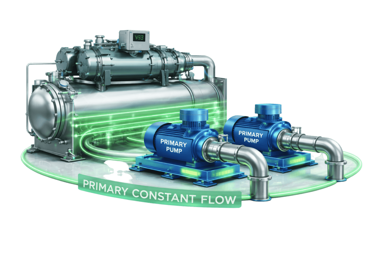
Primary Constant Flow Systems
Learn More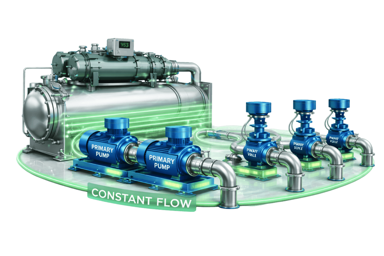
Constant Flow with Three-Way Valve Control
Learn More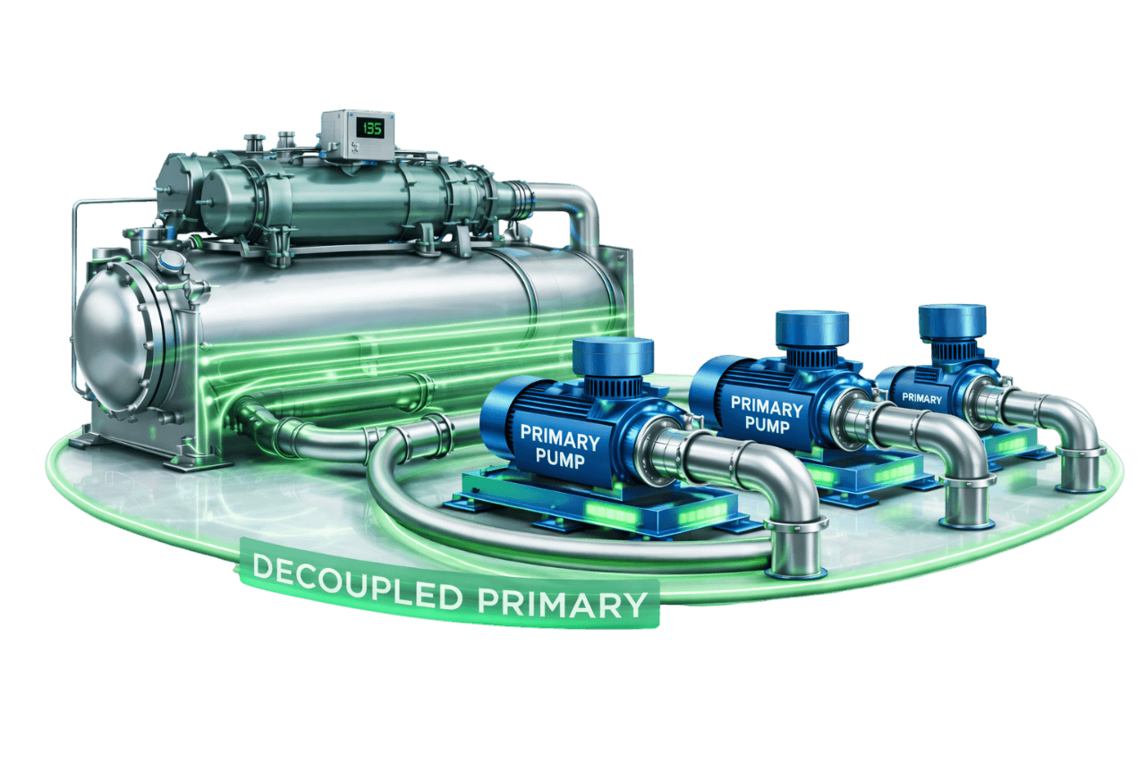
Decoupled Constant Primary Systems
Learn More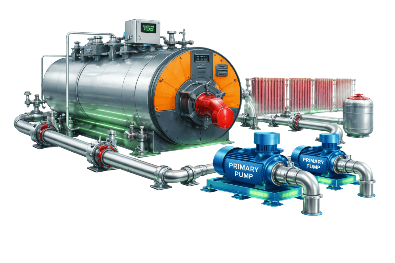
Boiler-Based Constant Flow Heating Systems
Learn MoreFrequently Asked Questions
Q1. What is a process cooling constant flow loop?
It is a recirculating cooling system in which constant speed pumps deliver a fixed flow of cooling water to production machines. The water then returns to a chiller, cooling tower or heat exchanger to be cooled again.
Q2. How does a constant flow process cooling system work?
A chiller cools water into a buffer tank. Process pumps then deliver a fixed flow from the tank to each machine through supply manifolds. Warmed water returns to the tank, and the chiller loop cools it again.
Q3. Why do process machines need constant flow?
Many machines are designed for a specific flow rate for effective heat transfer and temperature stability. Many also trip on low flow. Constant flow keeps them cooling correctly and protects product quality.
Q4. What is the difference between open-loop and closed-loop process cooling?
Open loops expose water to air through a tower or open tank, so they need stronger treatment and filtration. Closed loops are sealed and pressurized, which keeps water clean and protects machines from fouling.
Q5. Why is a buffer tank used in process cooling systems?
It adds thermal mass that stabilizes supply temperature, prevents chiller short cycling and hydraulically decouples the chiller and process loops.
Q6. How is a buffer tank sized for process cooling?
A common guide is about 11–38 litres of system water per TR, with the higher end for tight temperature control. For precise sizing, the tank must absorb a compressor's excess capacity during its minimum run time within the allowed temperature band.
Q7. What is a tank-based two-pump process cooling system?
A chiller loop pump circulates water between the tank and the chiller, while a separate process pump supplies the machines from the tank. Each loop runs at its own constant flow.
Q8. How is the process heat load calculated?
From equipment data, process calculations or measurement. Measured load equals 1.163 × flow (m³/h) × temperature rise (°C), giving kW.
Q9. How much cooling water flow does each process machine require?
It depends on the machine's heat load and allowed delta-T. Flow (m³/h) equals load (kW) divided by 1.163 × delta-T. Manufacturer data should always be checked first.
Q10. When is glycol required in a process cooling loop?
Glycol is needed when supply temperatures approach or fall below freezing, or when piping or equipment is exposed to freezing conditions. Examples include dairy, beverages, pharma and solvent recovery.
Q11. Should process cooling use chilled water or cooling tower water?
Use tower water wherever the process can accept around 30–32 °C, such as hydraulic oil coolers and compressors. Use chilled water where lower temperatures are required. Combining both usually gives the lowest running cost.
Q12. What piping material is best for process cooling lines?
It depends on the application. MS and GI suit general cooling water. SS suits pharma, food and deionized water. PPR offers corrosion-free runs, and HDPE suits large buried lines. GI should not be used with glycol.
Q13. What water treatment is required for process cooling loops?
Closed loops need soft or DM fill water, corrosion inhibitors and regular testing. Open loops and towers need scale inhibitors, biocides, blowdown control and filtration.
Q14. What is the difference between constant flow and variable flow process cooling?
Constant flow uses fixed-speed pumps delivering full flow at all times. Variable flow uses VFDs, typically holding manifold pressure constant. Running machines keep their design flow, while total pumping energy falls when machines are idle.
Q15. Can VFDs be used on process cooling pumps?
Yes. VFDs can hold constant manifold pressure as machines start and stop, or trim pumps to their exact design flow. Chiller minimum flow must still be protected.
Q16. Which industries use constant flow process cooling loops?
They are widely used in:
- plastics and moulding
- pharma, chemicals and food and dairy
- printing
- laser and CNC machining, die casting
- textiles, rubber and tyres
- electronics manufacturing
Q17. What are common problems in process cooling systems?
The most common problems are:
- insufficient flow at machines
- fluctuating supply temperature
- chiller trips
- scaling and clogging
- pump cavitation and seal failure
- tank level problems
- air entrainment
Q18. What maintenance does a process cooling system need?
Regular maintenance covers:
- chiller and heat exchanger cleaning
- pump and seal checks
- filter and strainer cleaning
- water treatment and glycol monitoring
- alarm and interlock testing
Q19. What information is needed for a process cooling system quotation?
We need:
- the machine list with cooling requirements
- required temperatures and tolerances
- operating hours
- existing equipment details
- the plant layout
- water quality
- piping preferences
- controls requirements
- expansion plans
Q20. Does Compress India design and install process cooling systems?
Yes. Compress India delivers complete process cooling constant flow loops across Mumbai, Maharashtra and India. Our scope covers:
- design and equipment selection
- piping, manifolds and water treatment
- PLC and SCADA controls
- commissioning and AMC
- upgrades and capacity expansion