Primary Constant Flow Systems
(Design, Installation, Commissioning, Retrofit & Lifecycle Support for Chilled Water Pumping Systems)
Primary Constant Flow Systems – Chilled Water Plant Engineering & Execution
Not every chiller plant needs complex variable flow controls. Small buildings, single-chiller plants and steady process loads are often best served by a well-designed primary constant flow system, which is a simple, dependable and cost-effective way to deliver chilled water. Many older buildings already run on constant flow, and the right upgrades can cut their energy bills without replacing the whole plant.
Compress India designs, installs, balances and upgrades primary constant flow chilled water systems for commercial, hospitality, healthcare and industrial facilities. We tell you plainly when constant flow is the right answer, and when a variable flow upgrade will pay for itself.
What we deliver:
- Constant flow chilled water system design, pump selection and pipe sizing
- Primary chilled water pumping systems with dedicated or headered pumps
- Three-way valve selection, balancing valves and complete testing, adjusting and balancing (TAB)
- Chiller-pump interlocks, chiller staging logic and BMS integration
- Retrofits to constant primary–variable secondary, variable primary flow or PICV-based distribution
- AMC and lifecycle support
Share your chiller and pump details with Compress India for a constant flow system review.
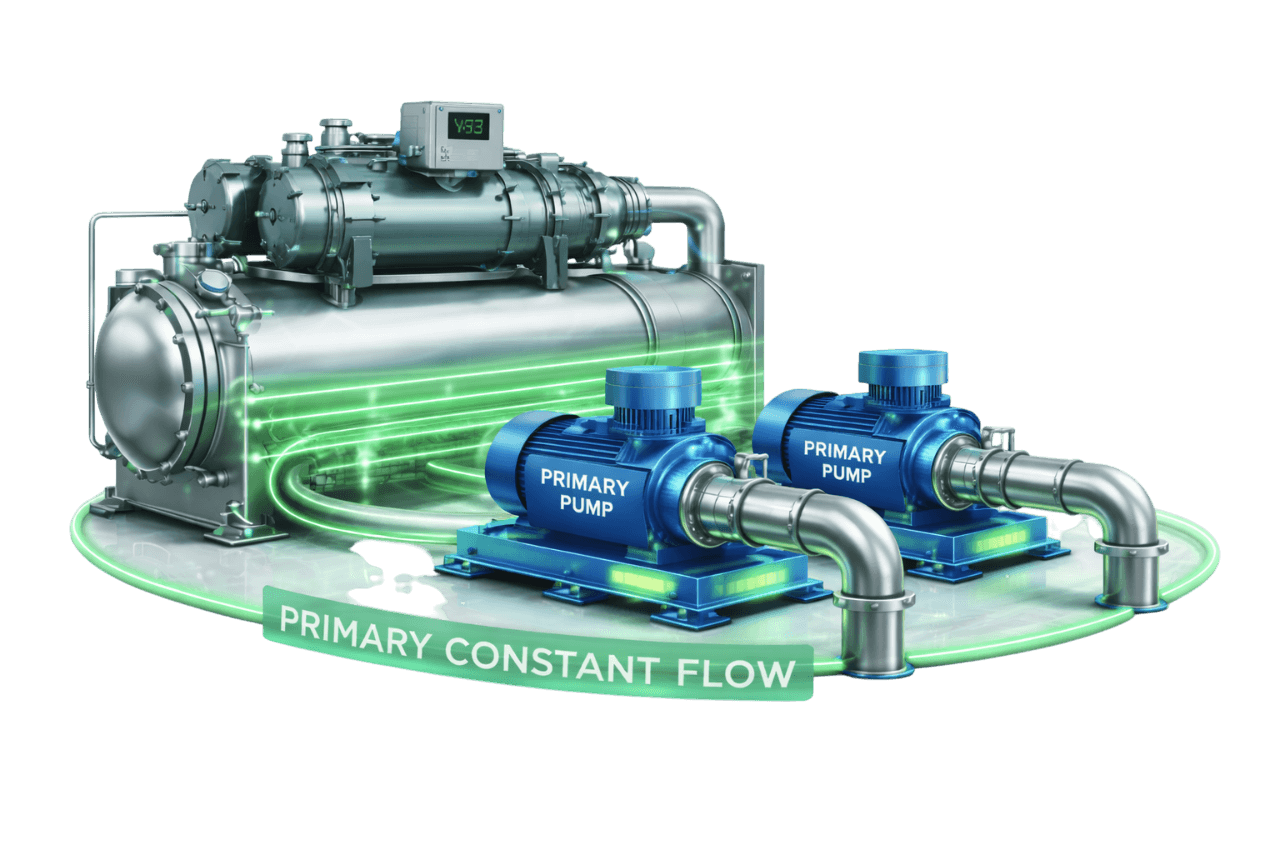
A constant flow system looks simple on paper, and that simplicity is its strength. It still only works well when the details are right:
- Pumps must be sized for the real system, not an inflated estimate.
- Every three-way valve bypass must be balanced to match its coil.
- Chillers must be interlocked with their pumps and staged sensibly.
Get these wrong and even a simple plant wastes energy and delivers uneven cooling.
Compress India handles every primary constant flow chiller plant as a complete engineering and execution project:
- 1. Load and site assessment: we confirm cooling loads, operating hours, space and future expansion plans.
- 2. Hydraulic design: we calculate design flows, pump head, pipe sizes and the index circuit.
- 3. Equipment selection: we select pumps, three-way valves, balancing valves, strainers and accessories.
- 4. Installation: we install pumps, headers, piping, valves, insulation and electrical connections.
- 5. Testing, balancing and commissioning: we balance every circuit, verify flows and set up chiller and pump controls.
- 6. Documentation and handover: you receive balancing reports, control sequences and operator training.
- 7. Lifecycle support: we provide AMC, performance reviews and upgrade planning.
What Is a Primary Constant Flow System?
A primary constant flow system is a chilled water distribution system in which constant speed pumps circulate a fixed quantity of water through the chillers and out to the building loads. Flow in the chilled water primary loop stays the same whatever the cooling load. The system is also known as a constant primary flow system or a constant flow chilled water system. Three-way valves at the AHUs and FCUs vary the water through each coil, while total flow stays constant.
As load falls, more water bypasses the coils and returns to the chillers unused. The chillers see cooler return water and unload their compressors, but the pumps keep running at full flow. This makes the constant primary flow chilled water system one of the simplest hydronic constant flow systems to design, build and operate. Every part of this primary constant flow chilled water distribution system is built around one idea: constant chilled water flow.
What Is a Primary-Only Chilled Water Pumping System?
A primary-only chilled water system uses a single set of pumps to move water through both the chillers and the building. There are no secondary pumps and no decoupler. The same chiller primary pump that pushes water through the evaporator also delivers it to every coil.
When those primary pumps run at constant speed, the result is a direct primary constant flow system, also called a direct primary chilled water system. When they run on VFDs with two-way valves at the coils, the system becomes a variable primary flow design. This page focuses on the constant flow version: a primary flow chilled water system in which flow never changes.
Why Constant Flow Systems Are Still Used
Variable flow systems dominate large new buildings, yet constant flow systems remain common. In the right application, they make practical sense:
- Simplicity: fewer controls, fewer sensors and fewer things to go wrong.
- Lower capital cost: constant speed pumps, three-way valves and basic controls cost less upfront.
- Chiller-friendly operation: evaporator flow never changes, so chillers operate exactly as designed.
- Small plants: in single-chiller plants with modest pumps, the energy penalty of constant flow is small in absolute terms.
- Steady loads: where the load hardly varies, as in many process applications, variable flow offers little benefit.
- Legacy installations: many existing buildings in India were built with constant flow systems and still need expert support.
How a Primary Constant Flow System Works
1. Constant Speed Primary Pumps Serving Chillers and Load
Each constant speed primary pump is started across the line or through a star-delta or soft starter. The pumps circulate a fixed flow through the chillers and the building distribution. Every pump runs at a single duty point, set during design and confirmed during balancing.
2. Constant Flow Through Chiller Evaporators
Each chiller receives a steady design flow through its evaporator. Chiller evaporator constant flow keeps heat transfer predictable and protects the chiller from low-flow trips and freezing risk.
3. Three-Way Control Valves at AHUs & FCUs
Each coil has a three-way valve controlled by a thermostat or DDC controller. As space or supply air temperature changes, the valve adjusts how much water passes through the coil and how much bypasses it.
4. Coil Bypass at Part Load
At part load, the three-way valve sends more water through its bypass leg. The coil receives less chilled water, but circuit flow, and therefore total system flow, stays constant.
5. Return Water Temperature–Based Chiller Control
System flow never changes, so return water temperature rises and falls directly with building load. Many constant flow plants use return water temperature, or supply-return delta-T, to decide how many chillers should run. Each running chiller controls its own leaving water temperature.
Main Components of a Primary Constant Flow System
| Component | Role in the System |
|---|---|
| Chillers | Produce chilled water at the design supply temperature |
| Constant speed primary pumps | Circulate a fixed flow through the chillers and the building |
| Standby pump | Takes over if a duty pump fails or needs maintenance |
| Suction and discharge headers | Distribute flow to and from pumps and chillers in headered designs |
| Three-way valves at AHUs and FCUs | Vary coil flow while keeping circuit flow constant |
| Balancing valves | Set design flow at each coil, bypass leg, branch and riser |
| Isolation valves, strainers and check valves | Allow maintenance, protect equipment and prevent backflow |
| Flow switches | Prove evaporator flow before a chiller starts |
| Expansion tank and air separator | Maintain system pressure and remove air |
| Supply and return temperature sensors | Measure load for chiller staging and monitoring |
| Pump starters and control panel | Start, stop and protect each primary CHW pump |
| BMS or chiller plant controller | Interlocks, staging, alarms and trending |
| Chiller bypass line, where fitted | Keeps chiller flow steady if some terminals have two-way valves or circuits are isolated |
Role of Three-Way Valves in Constant Flow Systems
Three-way valves are what make a 3 way valve chilled water system work. Together with their bypass legs, they form the chilled water bypass system that keeps flow constant. They are also the source of the system's biggest weakness.
Mixing vs Diverting Three-Way Valves
A mixing valve has two inlets and one outlet, combining two flows into one. A diverting valve has one inlet and two outlets, splitting one flow into two. In a coil circuit, either arrangement produces the same result: constant circuit flow with variable coil flow. The mixing valve sits on the return side and the diverting valve on the supply side. Mixing valves on the return are the most common HVAC arrangement, because they are widely available and handle the duty well.
Coil Bypass and Balancing
The bypass leg of each three-way valve needs a balancing valve set to match the coil's pressure drop. Without one, the bypass has less resistance than the coil. When the valve swings to bypass, that circuit takes more water than designed and starves circuits elsewhere.
Effect on Return Water Temperature
At part load, bypassed water leaves the circuit at supply temperature and mixes with warmer water from the coil. Return water temperature falls, delta-T shrinks and the chillers see less load for the same flow. This is the root cause of low delta-T in constant flow systems.
Types of Primary Constant Flow Configurations
Single Chiller with Single Pump
The simplest arrangement: one chiller, one pump, one loop. It suits very small plants where a short shutdown for pump maintenance is acceptable, but it offers no redundancy.
Single Chiller with Duty–Standby Pumps
One chiller is served by a duty pump and an equal standby pump. If the duty pump fails, the standby starts automatically. This is the minimum arrangement we recommend for occupied buildings.
Multiple Chillers with Dedicated Primary Pumps
Each chiller has its own pump, which starts and stops with it. Controls are simple, and each chiller receives exactly its design flow. The catch is that stopping a chiller and its pump reduces total system flow, which three-way valve distribution is not designed to handle.
Multiple Chillers with Headered Primary Pumps
All pumps discharge into a common header serving every chiller. Any pump can serve any chiller, and one standby can cover all duty pumps. The chillers need motorized isolation valves, and the flow split between running chillers must be managed carefully.
Parallel vs Series Chiller Arrangement
In a parallel arrangement, each chiller handles part of the flow and all of them produce the same supply temperature. In a series arrangement, the full flow passes through each chiller in turn. The first chiller sees warmer water and runs more efficiently, and the second completes the cooling. Series arrangements avoid blending problems and suit larger delta-T designs, but they add evaporator pressure drop and pump head.
Comparison Table – Dedicated vs Headered Constant Flow Pumps
| Parameter | Dedicated Pumps | Headered Pumps |
|---|---|---|
| Pump-to-chiller relationship | One pump per chiller | Any pump serves any chiller |
| Controls | Simple; the pump starts with its chiller | More complex; needs isolation valves and sequencing |
| Standby provision | Standby per pump, or crossover piping | One shared standby can cover all duty pumps |
| Flow to each chiller | Set by its own pump | Depends on header design and isolation valves |
| Stopping a chiller | Its pump stops and system flow drops | The chiller is isolated; the remaining chillers take the flow within their limits |
| Best suited for | Chillers of different sizes, simple plants | Identical chillers, larger plants |
Chiller Operation in Constant Flow Systems
Constant Evaporator Flow Requirement
Every chiller has minimum and maximum evaporator flow limits. Constant evaporator flow keeps the chiller comfortably inside them. A flow switch or differential pressure switch confirms flow before the compressor can start.
Chiller Capacity Control at Part Load
As return water cools at part load, the chiller unloads to hold its leaving water temperature. Each chiller type unloads differently:
- Scroll chillers stage compressors on and off.
- Screw chillers use slide valves or capacity steps.
- Centrifugal chillers use inlet guide vanes or variable speed drives.
Chiller Staging Challenges
In a multi-chiller constant flow plant, deciding when to stage chillers is harder than it looks. Return temperature indicates the load, but starting or stopping a chiller also shifts flows and temperatures across the plant. Poor staging leaves extra chillers running at low load, or allows supply water to warm up.
Supply Water Temperature Rise with Chillers Off (Blending)
In a parallel plant where water keeps flowing through an idle chiller, that water returns unchilled and blends with water from the running chiller.
Take two equal chillers at 50% load, with a 6.7 °C design supply temperature and half the flow passing through the idle chiller. The running chiller still holds 6.7 °C at its outlet, but the blended supply to the building rises to about 9.5 °C. That weakens dehumidification and comfort.
Isolating idle chillers, dedicated pumping or a series arrangement prevents it.
Benefits of Primary Constant Flow Systems
Simple Design & Operation
Fixed-speed pumps, three-way valves and straightforward interlocks mean fewer components and fewer settings. Operators understand the system quickly.
Stable Chiller Evaporator Flow
Chillers always see their design flow, which keeps capacity control stable and reduces nuisance trips.
Lower Initial Cost
With no VFDs, no secondary pumps, fewer sensors and simpler controls, capital cost stays down. That matters on small projects with tight budgets.
Minimal Controls & Instrumentation
The system needs only thermostats or DDC controllers, flow switches and a few temperature sensors. There are no differential pressure loops to tune.
Easy Maintenance
Constant speed pumps and simple starters are easy to service, and spares are widely available across India.
Suitable for Small Plants & Constant Process Loads
Where pumps are small or the load barely changes, constant flow delivers reliable cooling with an energy penalty that is modest in practice.
Limitations & Design Challenges
High Pumping Energy at Part Load
Pumps draw full power whether the building needs 100% or 30% of design cooling. On larger plants with long part-load hours, this adds up to significant wasted energy.
Low Delta-T at Part Load
Bypassed water lowers return temperature. At 50% load, delta-T is roughly half its design value, so the plant circulates twice as much water per TR as it really needs.
Reduced Chiller Plant Efficiency
Low delta-T and blending can force extra chillers to run lightly loaded. Meanwhile, pump kW per TR rises as load falls. Overall plant kW/TR worsens at exactly the loads where the plant spends most of its hours.
Chiller Staging & Supply Temperature Issues in Multi-Chiller Plants
In plants with two or more chillers, idle chillers can blend warm water into the supply, and staging decisions become harder. These problems grow with plant size.
Limited Scalability for Large Buildings
As buildings and plants grow, so do the energy penalty, balancing effort and staging problems of constant flow. Most large new buildings are better served by variable flow.
Energy Code Compliance Concerns
Energy codes generally require larger hydronic systems with modulating control valves to be capable of variable flow. Above certain system sizes, a constant flow design with three-way valves may not comply, so code requirements should be checked early.
Primary Constant Flow vs Constant Primary – Variable Secondary System
In a constant primary variable secondary system, also called a primary secondary chilled water system, the pumping is split into two loops. Constant speed primary pumps serve the chillers, while variable speed secondary pumps serve the building through two-way valves. A decoupler separates the two loops. This primary constant flow, secondary variable flow arrangement keeps chiller flow steady while building flow follows the load.
| Parameter | Primary Constant Flow | Constant Primary – Variable Secondary |
|---|---|---|
| Pumps | One set of constant speed pumps | Constant primary pumps plus variable speed secondary pumps |
| Terminal valves | Three-way | Two-way or PICVs |
| Building flow | Constant | Variable |
| Chiller flow | Constant | Constant for each running chiller |
| Blending with idle chillers | Possible in parallel plants | Avoided, because each chiller's pump stops with it |
| Pumping energy at part load | High | Lower on the secondary side |
| Capital cost | Lower | Higher |
| Best suited for | Small, simple plants | Medium to large buildings, multi-chiller plants |
For many existing plants, the constant primary variable secondary chilled water system is the most natural upgrade path. The primary secondary pumping system keeps existing chillers and primary pumps in service while adding variable flow on the building side.
Primary Constant Flow vs Variable Primary Flow (VPF) System
The difference between constant primary flow and variable primary flow comes down to what the pumps do at part load. In a VPF system, a single set of VFD pumps varies flow through both the chillers and the building, and a bypass valve maintains chiller minimum flow.
| Parameter | Primary Constant Flow | Variable Primary Flow |
|---|---|---|
| Pump speed | Constant | Variable, through VFDs |
| Terminal valves | Three-way | Two-way or PICVs |
| Chiller evaporator flow | Constant | Varies within chiller limits |
| Minimum flow protection | Inherent | Bypass valve with flow measurement |
| Pumping energy | Highest | Lowest |
| Controls complexity | Low | High |
| Number of pump sets | One | One |
| Capital cost | Lowest | Moderate |
Primary Constant Flow vs PICV Based Variable Flow Distribution
In a PICV based system, every terminal has a pressure independent control valve that balances and controls its own flow, while VFD pumps follow demand.
| Parameter | Primary Constant Flow | PICV Based Variable Flow |
|---|---|---|
| Terminal control | Three-way valves with manual balancing | PICVs with automatic dynamic balancing |
| Flow at part load | Constant, with bypassing | Follows the load |
| Balancing | Proportional balancing required | Preset and verify |
| Delta-T | Falls at part load | Held close to design |
| Pumping energy | High | Low |
| Comfort control | Good when well balanced | Consistent at all loads |
| Capital cost | Lower | Higher |
| Expansion | Rebalancing required | Terminals added without rebalancing |
When Is a Primary Constant Flow System the Right Choice?
Constant flow is not outdated; it is specialized. Here is where it still makes sense.
Small Buildings & Single-Chiller Plants
Small offices, clinics and showrooms with one chiller and small pumps get reliable cooling from a constant flow system at the lowest cost. The energy difference stays limited because pump power is small.
Constant Process Cooling Loads
Many process loads run at steady output for hours at a time. With little load variation, constant flow matches demand naturally and keeps process temperatures stable.
Budget-Constrained Projects
When capital is tight, a constant flow system gets the project running. We design it for future conversion, with space and piping connections planned for secondary pumps or VFDs.
Existing Legacy Systems
Many older buildings run constant flow plants whose chillers still have years of life left. Optimizing these systems through rebalancing, impeller trimming and targeted upgrades often makes more sense than full replacement.
ECBC & ASHRAE 90.1 Considerations for Constant Flow Systems
Energy codes have steadily moved chilled water design towards variable flow. Above certain size thresholds, India's Energy Conservation Building Code (ECBC) and ASHRAE Standard 90.1 generally expect two things from hydronic systems with modulating control valves:
- flow that varies with load
- pump power that falls at part load, typically through variable speed drives
A constant flow system with three-way valves does neither. What this means in practice:
- Small systems may fall below code thresholds or qualify for exceptions, depending on the edition and system size.
- Larger new systems designed for constant flow will usually struggle to comply and should be reviewed early with the MEP consultant.
- Existing buildings may trigger code requirements during major renovations or plant replacement, which is often the right moment to convert to variable flow.
- Green building projects under IGBC, GRIHA or LEED typically benefit from the lower energy use of variable flow.
Compress India checks code applicability at the design stage, so there are no surprises at approval or certification.
Primary Constant Flow Systems for HVAC
In HVAC, primary constant flow systems serve small commercial buildings, showrooms, clinics, restaurants and older buildings with established constant flow plants. A constant flow system for AHU and FCU circuits uses a three-way valve at each coil. Its AHUs often deliver constant air flow through fixed-speed supply fans, while the coil valve modulates cooling. This constant flow chilled water distribution approach is the simplest form of HVAC chilled water distribution.
Compress India designs and installs these systems with correctly sized pumps, balanced three-way circuits and reliable chiller-pump interlocks, giving each building a dependable primary chilled water distribution system. For larger or older HVAC plants, we also identify where variable flow upgrades will reduce running costs across the whole HVAC hydronic distribution.
Primary Constant Flow Systems for Industrial & Process Cooling
Process cooling is where constant flow systems often perform best. Injection moulding machines, extruders, compressors, test rigs and heat exchangers frequently need a steady, predictable flow of chilled water at a fixed temperature. A constant flow chiller plant pumping system delivers exactly that, with minimal controls.
For industrial constant flow systems, we design in:
- robust pumps with standby capacity
- strainers suited to process water
- buffer tanks, where needed, to stabilize chiller operation
- interlocks with production equipment
The result is a chilled water circulation system that production teams can rely on shift after shift.
Applications of Primary Constant Flow Systems
Small Commercial Buildings & Offices
Single-chiller plants in small offices and commercial buildings are the classic constant flow application. They are simple to run, economical to build and easy to maintain.
Showrooms & Retail Outlets
Automobile showrooms, standalone stores and small retail buildings have steady loads through trading hours. They suit constant flow chilled water, often with a single air-cooled chiller and duty-standby pumps.
Small Hospitals & Clinics
Smaller healthcare facilities value simplicity and reliability. A constant flow system with duty-standby pumps provides dependable cooling with minimal control complexity.
Hotels & Restaurants
Small hotels, restaurants and banquet facilities with compact plants use constant flow for FCUs and dining or kitchen AHUs. Three-way valves keep chiller flow stable as occupancy changes.
Manufacturing & Process Cooling
Factories with steady process loads use constant flow to supply machines, heat exchangers and process equipment with consistent flow and temperature.
Plastic & Injection Moulding Units
Moulding machines need stable chilled water flow to control cycle times and product quality. Constant flow systems with buffer tanks and dedicated pumps are widely used in plastic processing units.
Laboratories
Laboratory equipment and small process loads often need steady cooling water. Constant flow systems provide predictable temperature and flow for sensitive instruments.
Legacy Buildings with Existing Constant Flow Plants
Older buildings across India still run constant flow plants. We optimize them for better performance, or convert them to variable flow when the numbers justify it.
Primary Constant Flow Systems with Screw, Scroll & Centrifugal Chillers
Constant flow works with every common chiller type, but each brings its own considerations:
- Scroll chillers: used in smaller plants, with multiple compressors staging on and off. When system water volume is low, they can short-cycle at light load, so a buffer tank or adequate loop volume is often needed.
- Screw chillers: common in medium plants, with slide valve or stepped capacity control. They handle constant flow well and give good part-load efficiency when the plant is correctly balanced.
- Centrifugal chillers: used in larger plants. They have long operated with constant evaporator flow, but at their size the energy penalty of constant flow pumping becomes significant. Larger centrifugal plants are therefore often better served by primary-secondary or variable primary designs.
Whatever the chiller type, we confirm evaporator flow limits, pressure drops and minimum water volume against the manufacturer's data before finalizing the pumping design.
System Design & Sizing
Good constant flow chilled water system design, like any primary chilled water pumping system design, depends on accurate flows and realistic pressure drops. The pumps will run at the design point for every hour of their life.
Chilled Water Flow Calculation (GPM / m³/hr per TR)
Chilled water flow depends on load and delta-T:
GPM = (TR × 24) ÷ ΔT (°F) Flow (m³/h) ≈ (TR × 3.02) ÷ ΔT (°C)
| Delta-T | GPM per TR | m³/h per TR |
|---|---|---|
| 8 °F (4.4 °C) | 3.0 | 0.68 |
| 10 °F (5.6 °C) | 2.4 | 0.55 |
| 12 °F (6.7 °C) | 2.0 | 0.45 |
| 14 °F (7.8 °C) | 1.7 | 0.39 |
| 16 °F (8.9 °C) | 1.5 | 0.34 |
For example, a 200 TR plant designed for a 10 °F delta-T needs about 480 GPM, or roughly 109 m³/h.
Primary Pump Head Calculation
Pump head is the total pressure loss around the highest-resistance path at design flow. It includes:
- the chiller evaporator pressure drop
- supply and return pipe friction and fittings to the index terminal
- the index coil, its three-way valve and its balancing valve
- strainers, check valves, isolation valves and plant accessories
Add a modest margin, but avoid stacking safety factors. In a constant flow system, an oversized pump burns its excess head every operating hour.
Chilled Water Delta-T Selection
Many Indian plants are designed for a 10 °F (about 5.6 °C) delta-T. Choosing a higher delta-T, with coils selected to match, reduces flow, pipe sizes and pump power. Remember that in a constant flow system, design delta-T is reached only at full load. At part load it falls in proportion to the load.
Three-Way Valve Sizing
Three-way valves are sized on flow and pressure drop, not pipe size. A common target is a valve pressure drop similar to the coil's, which gives good control authority. The required flow coefficient is:
Kv = Flow (m³/h) ÷ √ΔP (bar)
A 30 TR AHU needs about 16.5 m³/h. With a 0.4 bar target, the required Kv is about 26, so a Kvs 25 valve would give roughly 0.44 bar.
Header and Pipe Sizing
Pipes are sized for design flow using sensible velocity and friction limits, balancing pump head against pipe cost. Headers are sized for low velocities so flow divides evenly between pumps and chillers. Because design flow is the operating flow for every hour, correct pipe sizing pays back continuously.
Pump Redundancy Selection
A duty-standby arrangement is the minimum for occupied buildings. Multi-chiller plants can use a standby pump per chiller with dedicated pumping, or a shared standby with headered pumping. Critical facilities may justify N+1 on every duty group.
Pump Selection Criteria
End-Suction vs Split-Case Pumps
End-suction pumps are compact and economical for small to medium flows. Split-case pumps suit larger flows, offer higher efficiency and let the rotating assembly be serviced without disturbing the piping. We select between them based on flow, head, efficiency and plant room space.
Inline Pumps
Vertical inline pumps save floor space and install directly in the pipework. They are a practical choice for compact plant rooms and small constant flow systems.
Pump Efficiency and Best Efficiency Point (BEP)
A constant speed chilled water pump runs at one operating point for its entire life. That makes selecting it at or very near its BEP more important than in any other system type. We match the pump curve to the verified system curve, so the pump runs efficiently every hour it operates.
IE3 / IE4 Motor Selection
Constant flow pumps run at full load continuously, so motor efficiency translates directly into energy cost. IE3 motors are the practical minimum. IE4 motors pay back quickly on pumps with long running hours.
Piping Layout & Plant Room Arrangement
Primary Loop Piping
The constant flow primary loop connects pumps, chillers and distribution headers with clean, logical routing. We arrange equipment for even flow distribution, easy isolation and safe access.
Direct Return vs Reverse Return Piping
In direct return piping, the first terminal on the supply is also the first on the return. Near circuits therefore have shorter paths and need throttling to balance. Reverse return piping equalizes path lengths and makes the system largely self-balancing, at the cost of extra pipe. On long floors and risers in constant flow systems, reverse return can cut balancing effort significantly.
Balancing Valves for Constant Flow Systems
Every coil circuit, bypass leg, branch and riser needs a balancing valve to set its design flow. In constant flow systems, flows don't change with load. Once balancing is set correctly, it stays valid until the system is modified.
Valves, Strainers, Check Valves & Flexible Connections
Isolation valves allow each pump and chiller to be serviced. Strainers protect pumps and chiller tubes, check valves prevent reverse flow through idle pumps, and flexible connections keep vibration out of the piping.
Insulation of Chilled Water Piping
All chilled water piping, valves and fittings need vapour-sealed insulation to prevent condensation and heat gain. In Mumbai's humid climate, any gap in the insulation quickly leads to dripping, corrosion and wasted cooling.
Water Balancing in Constant Flow Systems
Balancing is where a constant flow system is made or broken. Because flows never change, a properly balanced system stays balanced for years.
Proportional Balancing Method
Proportional balancing works in three stages. First, every terminal in a branch is set to the same percentage of its design flow, starting from the index circuit. Next, the branches are balanced against each other. Finally, the main flow is set at the pump. Because each adjustment affects the others proportionally, the method reaches design flows in far fewer iterations than trial and error.
Balancing Valve Selection & Setting
Balancing valves are selected to produce enough differential pressure at design flow for an accurate reading; manufacturers typically recommend a minimum of a few kPa. Oversized valves read poorly and are hard to set. Final settings are recorded and locked.
Flow Measurement Using Balancing Valves
Flow is measured by connecting a balancing instrument to the valve's test points. The instrument reads differential pressure and calculates flow from the valve's characteristics at its current setting. Readings go into the TAB report as the permanent reference for the system.
Controls, Automation & BMS Integration
Chiller–Pump Interlocking
The chilled water pump must start first and prove flow through a flow switch before the chiller is allowed to start. When the chiller stops, the pump runs on for a set time so the evaporator isn't left with stagnant water while refrigerant pressures settle. These interlocks protect the evaporator and underpin safe plant operation.
Three-Way Valve Control at Terminal Units
Each three-way valve is modulated by a room thermostat, FCU controller or AHU DDC controller to hold space or supply air temperature. Correct valve sizing and tuning prevent temperature hunting.
Chiller Staging Logic
Staging logic decides how many chillers run, using return water temperature, supply-return delta-T or calculated load. Time delays prevent short cycling. In parallel plants, idle chillers are isolated, or their pumps stopped, to avoid blending.
Pump Status Monitoring & Alarms
Every pump's run status, trip alarms, flow switch status and run hours are monitored. Automatic changeover to the standby pump on a trip keeps the plant running.
BMS Integration & Remote Monitoring
Chillers, pumps and temperature sensors are integrated with the BMS over BACnet, Modbus or hardwired points. Operators see live status, trends and alarms, and remote access speeds up troubleshooting.
Energy Efficiency & Power Consumption
Understanding where the energy goes is the first step to reducing it.
Pumping Energy Calculation
Pump power is calculated as:
Pump power (kW) = Flow (m³/h) × Head (m) ÷ (367 × combined pump-motor efficiency)
Consider a 200 TR plant circulating 109 m³/h at 30 m head with 70% combined efficiency. Its pumps draw about 12.7 kW. In a constant flow system, that power is drawn every running hour: at 4,000 hours a year, roughly 51,000 kWh.
Plant kW/TR Calculation
Plant kW/TR is calculated as:
Plant kW/TR = Total plant power (chillers, pumps and cooling tower fans) ÷ Cooling delivered (TR)
Cooling delivered comes from flow and delta-T: TR = Flow (m³/h) × ΔT (°C) ÷ 3.02. In the example above, the pumps alone add about 0.064 kW/TR at full load. At 50% load, pump power is unchanged but the load halves, so the pumps' share doubles to about 0.13 kW/TR.
Energy Improvement Opportunities
Even without converting to variable flow, constant flow plants can often be improved:
- Trim oversized pump impellers instead of throttling discharge valves
- Run pumps only with their chillers, where the system allows
- Rebalance to remove overflowing circuits
- Clean strainers, coils and chiller tubes
- Raise supply temperature where dehumidification allows
- Upgrade to IE3 or IE4 motors
When the savings justify it, converting to variable flow delivers the biggest step change.
Installation of Primary Constant Flow Systems
Compress India installs primary constant flow systems in a planned sequence:
- 1. Plant room planning: we fix equipment layout, access routes, foundations and maintenance clearances.
- 2. Pump installation: we set pumps on inertia bases or plinths, then level and align them.
- 3. Piping and headers: we install, support and pressure test the primary loop, headers and distribution piping.
- 4. Valves and accessories: we fit isolation valves, strainers, check valves, flexible connections, balancing valves and three-way valves.
- 5. Electrical works: we install pump starters, the control panel, cabling and earthing.
- 6. Controls: we install flow switches and temperature sensors, and wire chiller-pump interlocks and BMS connections.
- 7. Flushing and filling: we flush, clean, treat, fill and vent the system.
- 8. Insulation: after pressure testing, we insulate all chilled water piping, valves and fittings.
Testing, Balancing & Commissioning (TAB)
Commissioning a constant flow system centres on water balancing. Our TAB process covers:
- Pre-commissioning checks: pump rotation, alignment, electrical protection, valve positions and system venting
- Pump performance verification: flow and head checked against the pump curve
- Proportional balancing: every coil, bypass leg, branch and riser set to design flow
- Three-way valve verification: full coil flow and full bypass flow checked to confirm balanced bypasses
- Chiller flow verification: evaporator flow and pressure drop confirmed against design
- Interlock and staging tests: pump-chiller interlocks, flow switches, standby changeover and staging logic
- TAB report: measured flows, valve settings and pump data documented for handover
Maintenance & AMC for Constant Flow Chilled Water Systems
Constant flow systems are simple, but they still need regular care to stay efficient. Compress India's AMC typically includes:
- Pump inspections covering vibration, bearings, seals, alignment and motor insulation
- Strainer cleaning at pumps, chillers and terminal units
- Three-way valve and actuator checks for leakage, stroke and control response
- Balancing checks at key circuits, with rebalancing after any system changes
- Chiller evaporator flow and pressure drop checks
- Water treatment monitoring to prevent scale and corrosion
- Insulation inspection and repair
- Performance reviews of delta-T, pump power and plant kW/TR trends
AMC plans can be comprehensive or non-comprehensive.
Common Problems & Troubleshooting
Low Delta-T at Part Load
Low delta-T at part load is inherent to constant flow with three-way valves. It gets worse when bypasses are unbalanced, coils are fouled or supply temperatures are set too low. Rebalancing, coil cleaning and a setpoint review help, and converting to variable flow solves it.
High Pumping Energy Consumption
Common causes are oversized pumps throttled by discharge valves, pumps running without their chillers, and excess resistance from choked strainers. Impeller trimming, proper sequencing and regular maintenance bring consumption down.
Chilled Water Supply Temperature Rise
The usual causes are blending through idle chillers, a chiller capacity shortfall or fouled evaporator tubes. Isolating idle chillers, stopping their pumps where possible and restoring chiller performance fix the problem.
Unbalanced Flow Between Terminal Units
When balancing valves are missing, wrongly set or disturbed, near circuits overflow and remote circuits starve. Proportional rebalancing restores design flows.
Three-Way Valve Failure or Leakage
A three-way valve stuck in bypass starves its coil, while one stuck through the coil overcools the space. Internal leakage reduces control accuracy. Actuator checks, valve servicing or replacement correct these faults.
Pump Cavitation & Vibration
Cavitation often comes from low suction pressure, blocked strainers, air in the system or a pump running far right of its curve. Vibration can also come from misalignment or worn bearings. Checking system pressurization, cleaning strainers, venting air and realigning the pump resolve most cases.
Retrofitting & Upgrading Constant Flow Systems
A constant flow plant that uses too much energy, or struggles with low delta-T and blending, can be transformed by an upgrade without replacing the chillers.
Converting to Constant Primary – Variable Secondary
The primary pumps stay with the chillers, a decoupler is added, and new variable speed secondary pumps serve the building through two-way valves or PICVs. For multi-chiller plants, this is often the lowest-risk conversion.
Converting to Variable Primary Flow
Existing or new primary pumps are fitted with VFDs and terminal valves are converted to two-way. A bypass valve with flow measurement then protects chiller minimum flow. Before recommending VPF, we confirm each chiller's flow limits and rate-of-change tolerance with the manufacturer.
Replacing Three-Way Valves with Two-Way Valves / PICVs
Replacing three-way valves turns the building side into variable flow. If the pumps stay constant speed, a bypass must maintain chiller and pump minimum flow, so valve replacement is best paired with pump upgrades. Some designs keep a few three-way valves at the ends of long runs to keep water moving.
Adding VFDs to Existing Pumps
In a true constant flow system, a VFD saves energy by setting the pump to its exact design flow instead of throttling excess head across a valve. The major savings come when VFDs are combined with two-way valves and differential pressure control.
Impeller Trimming for Oversized Pumps
Many constant flow pumps are oversized and throttled back to design flow. Trimming the impeller, within the manufacturer's allowable range, matches the pump to the system permanently and cuts power, often with a very short payback.
Is your constant flow plant costing more than it should? Ask Compress India for an upgrade assessment.
Primary Constant Flow System Cost in India
The cost of a primary constant flow system depends on plant capacity, the number of chillers and pumps, the extent of piping and the control requirements. A single-chiller showroom plant is a very different investment from a multi-chiller legacy plant upgrade.
Compress India prepares itemized proposals covering equipment, piping, installation, balancing and controls. For larger plants, we compare constant flow and variable flow options side by side, so you can weigh capital cost against running cost.
Factors Affecting Project Cost
- Plant capacity and number of chillers
- Number, type and size of pumps, including standby
- Dedicated or headered pumping arrangement
- Length and size of chilled water piping and headers
- Number of AHUs and FCUs with three-way and balancing valves
- Pipe insulation specification
- Electrical starters, control panel and BMS integration
- Water treatment and system flushing
- Testing, balancing and commissioning scope
- Retrofit constraints, shutdown windows and site access
- AMC requirements
Information Required for a Quotation
To prepare an accurate proposal, please share:
- Building type, cooling load and operating hours
- Chiller details: number, capacity, type, and evaporator flow and pressure drop
- Existing or proposed pump schedule
- Number and type of terminal units, with AHU and FCU capacities
- Chilled water schematic or piping layout
- Plant room layout, drawings or photographs
- Control and BMS requirements
- For existing plants: current problems, energy bills, pump nameplates and valve types
- Future expansion plans
- Project timeline
Don't have all of this? Our engineers can collect it during a site visit.
Primary Constant Flow System Contractor in Mumbai
Looking for a primary constant flow system contractor in Mumbai? Compress India designs and installs new constant flow chilled water systems and upgrades existing ones across the city. Mumbai has a large stock of older commercial buildings, hotels and hospitals running constant flow plants. Many have oversized pumps, worn three-way valves and balancing that has been disturbed over the years.
We help these buildings in two ways: optimizing the existing constant flow system, or planning a phased conversion to variable flow. For new small projects such as showrooms, clinics and restaurants, we deliver compact, well-balanced constant flow plants.
We work across Mumbai, including Colaba, Churchgate, Dadar, Sion, Chembur, Ghatkopar, Andheri, Jogeshwari and Kandivali.
Book a site visit with Compress India for your constant flow chilled water system.
Chilled Water Pumping Solutions in Mumbai, Navi Mumbai, Thane & Maharashtra
Compress India supports chilled water pumping projects across Mumbai and the wider region. In Navi Mumbai, we cover Vashi, Turbhe, Rabale, Mahape, Kharghar and Taloja MIDC. In Thane, we cover Wagle Estate, Kolshet, Balkum and Ghodbunder Road. Elsewhere, we work in Bhiwandi, Vasai-Virar, Palghar, Boisar-Tarapur, Pune, Nashik, Nagpur and Chhatrapati Sambhajinagar. Our solutions include:
- New constant flow plants: single and multi-chiller plants for small commercial, hospitality and healthcare projects
- Process cooling: constant flow systems for moulding, pharma, food processing and engineering units
- Water balancing and TAB: rebalancing of existing constant flow systems
- Pump replacement and optimization: right-sized pumps, impeller trimming and efficient motors
- Conversions: constant primary–variable secondary, variable primary flow and PICV upgrades
- AMC: pumps, valves, balancing and water treatment coordination
Primary Constant Flow System Solutions Across India
Compress India also takes up constant flow projects and upgrades beyond Maharashtra. These include commercial centres such as Delhi NCR, Bengaluru, Hyderabad, Chennai and Kolkata, and industrial hubs such as Ahmedabad, Vadodara, Vapi, Coimbatore and Ludhiana. Many of these industrial clusters rely on steady process cooling, where a well-designed constant flow plant is often the most practical solution.
Wherever the project is, we apply the same design checks, balancing procedures and commissioning standards. For businesses with plants in several locations, this means consistent performance and documentation across every site.
Why Choose Compress India for Primary Constant Flow Systems?
Hydraulic Design Expertise
We calculate real flows and pressure drops rather than relying on rules of thumb, so your pumps are sized for the system you actually have.
Complete Chiller Plant Integration
Chillers, pumps, valves and controls are designed as one plant, with proper interlocks, staging and flow protection.
Pump Selection Support
We select pumps at their best efficiency point, with the right motor class and redundancy for your application.
Water Balancing & TAB
Our balancing teams set every coil, bypass and branch to design flow and document the results for future reference.
Installation & Commissioning
From plinths and piping to starters and sensors, our execution team installs and commissions the complete system.
Retrofit & Energy Optimization
We know when to optimize a constant flow plant and when to convert it. We then deliver the upgrade in phases, with minimal disruption.
AMC & Lifecycle Support
Regular maintenance, balancing checks and performance reviews keep your plant reliable and efficient throughout its life.
How to Choose Between Constant Flow and Variable Flow Systems
Choosing between a constant flow and a variable flow chilled water system depends on plant size, load profile, budget and energy targets.
Choose constant flow when:
- The plant has a single chiller and small pumps
- Loads are steady, as in many process applications
- Capital budget is the main constraint
- Simple operation matters more than maximum efficiency
Choose variable flow when:
- The plant has multiple chillers or large pumps
- The building spends long hours at part load
- Energy costs are high or green building targets apply
- Energy code compliance requires it
Here is how constant speed and variable speed pumps compare in HVAC:
| Parameter | Constant Speed Pump | Variable Speed Pump |
|---|---|---|
| Flow | Fixed | Follows demand |
| Energy at part load | Full power | Reduced sharply |
| Starting | DOL, star-delta or soft starter | Soft start through the VFD |
| Controls | Simple | Requires DP or flow control |
| Capital cost | Lower | Higher |
| Best for | Small plants, steady loads | Variable loads, larger plants |
Not sure which fits your building? A short site assessment will show which system gives the best balance of cost and performance.
Get a Primary Constant Flow Solution from Compress India
Whether you need a new constant flow plant, a better-balanced existing system or a planned move to variable flow, Compress India delivers it with one accountable team.
Connect with Our HVAC Execution Team
Call our team or send an enquiry through this page with your chiller, pump and terminal unit details. Our engineers will review your system and recommend a site visit where needed. We will then prepare a clear proposal with design, cost and performance options.
Related Systems Types & Components
Explore our comprehensive range of hydronic system configurations and components designed for efficient water distribution.
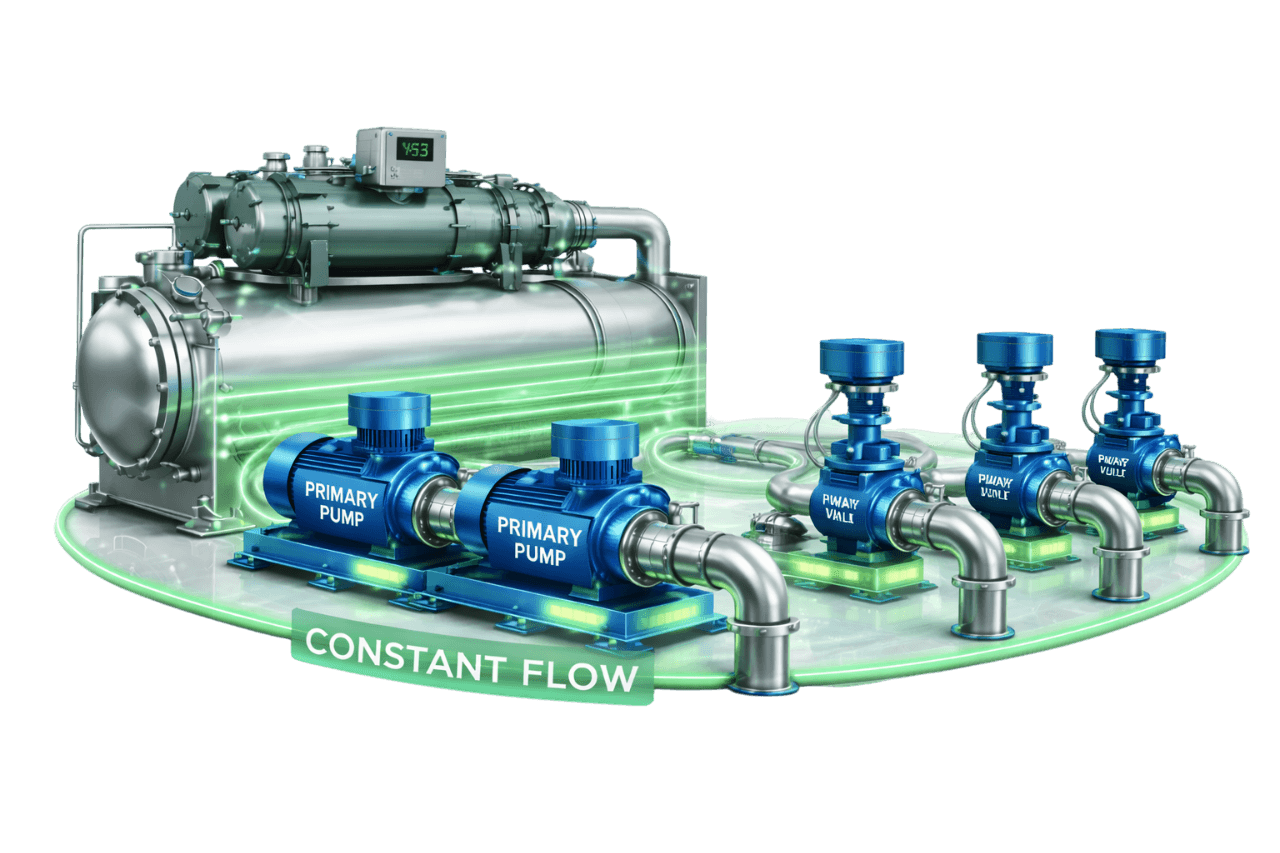
Constant Flow with Three-Way Valve Control
Learn More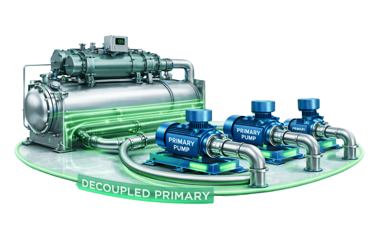
Decoupled Constant Primary Systems
Learn More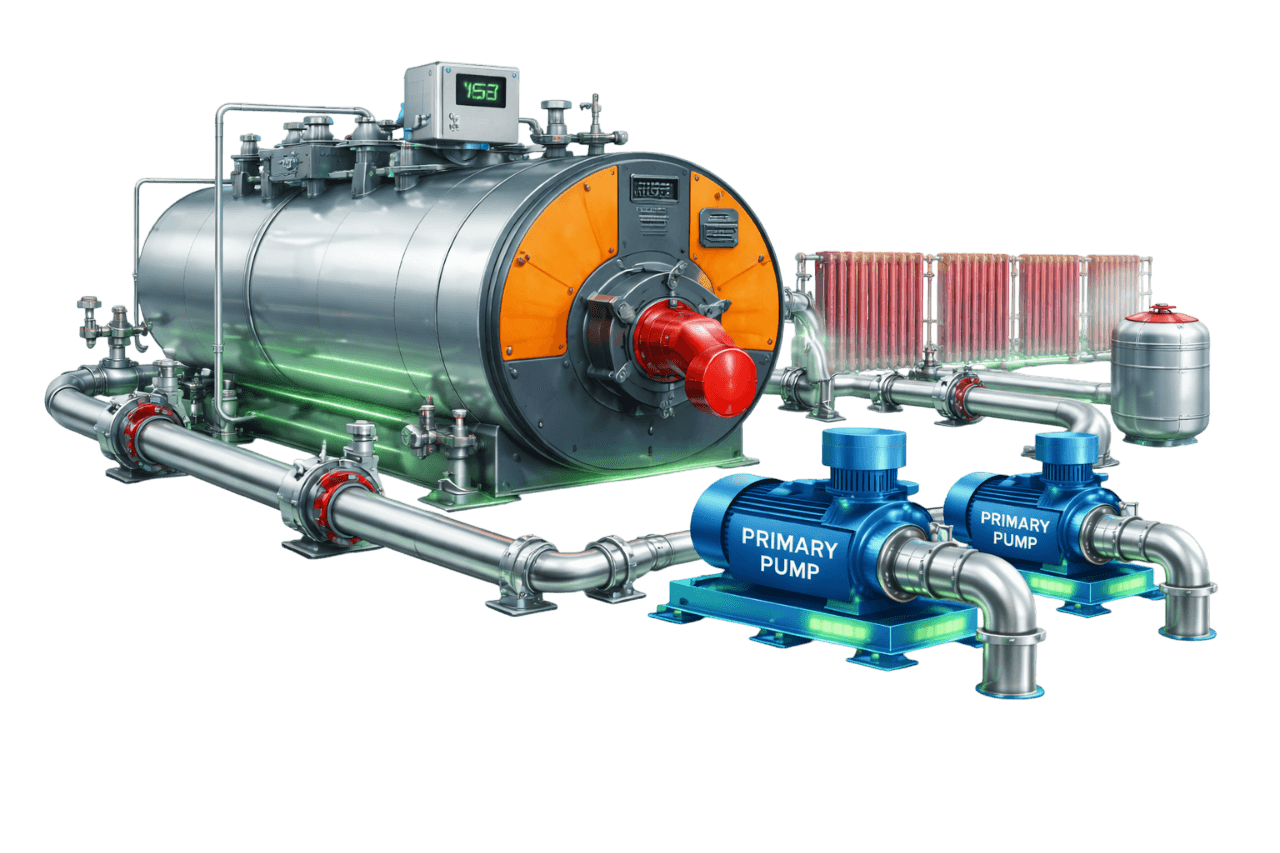
Boiler-Based Constant Flow Heating Systems
Learn More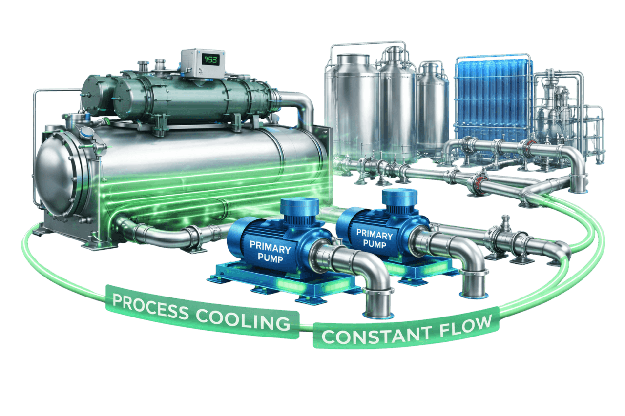
Process Cooling Constant Flow Loops
Learn MoreFrequently Asked Questions
Q1. What is a primary constant flow system?
It is a chilled water system in which constant speed primary pumps circulate a fixed flow through the chillers and directly to the building's AHUs and FCUs. Three-way valves at the coils vary coil flow while total system flow stays constant.
Q2. How does a primary constant flow chilled water system work?
Constant speed pumps push design flow through the chillers and distribution. At each coil, a three-way valve sends water through the coil or its bypass according to demand. As load drops, return temperature falls and the chillers unload to hold their supply temperature.
Q3. Why are three-way valves used in constant flow systems?
They keep the flow through each circuit constant while varying the flow through the coil. This protects the chillers from flow changes and keeps constant speed pumps at a stable operating point.
Q4. What is the difference between mixing and diverting three-way valves?
A mixing valve combines two inlet flows into one outlet; a diverting valve splits one inlet flow into two outlets. In a coil circuit, a mixing valve on the return and a diverting valve on the supply give the same result. Mixing valves on the return are the more common arrangement.
Q5. Do primary constant flow systems use VFD pumps?
Not to vary flow. A VFD can serve as a fixed-speed setting that delivers the exact design flow instead of throttling. Once pump speed varies with load, the system becomes a variable flow system.
Q6. What are the advantages of a primary constant flow system?
The main advantages are:
- simple design and operation
- stable chiller evaporator flow
- lower initial cost
- minimal controls
- easy maintenance
- a good fit for small plants and steady process loads
Q7. What are the disadvantages of a primary constant flow system?
The main disadvantages are:
- high pumping energy at part load
- low delta-T
- reduced plant efficiency
- blending and staging issues in multi-chiller plants
- limited scalability
- possible energy code compliance concerns on larger systems
Q8. Why does low delta-T occur in constant flow systems?
At part load, three-way valves bypass supply water around the coils. That cold water mixes with coil return water and lowers the return temperature. With flow fixed, delta-T falls in proportion to the load.
Q9. What happens to supply water temperature when one chiller is turned off?
In a parallel plant, water that keeps flowing through the idle chiller returns unchilled and blends with the running chiller's output. With two equal chillers at 50% load, supply can rise from 6.7 °C to about 9.5 °C. Isolating idle chillers or stopping their pumps prevents this.
Q10. What is the difference between primary constant flow and constant primary – variable secondary systems?
A primary constant flow system uses one set of constant speed pumps for both chillers and building. A constant primary–variable secondary system adds variable speed secondary pumps for the building, separated from the chiller loop by a decoupler. Building flow varies while chiller flow stays constant.
Q11. What is the difference between constant flow and variable primary flow?
In constant flow, pumps run at fixed speed and flow never changes. In variable primary flow, VFD pumps vary flow through both chillers and building, and a bypass protects chiller minimum flow. The result is much lower pumping energy.
Q12. When is a primary constant flow system the right choice?
It suits:
- small buildings and single-chiller plants
- steady process loads
- budget-constrained projects
- existing legacy systems that still have useful life
Q13. Is a primary constant flow system suitable for process cooling?
Yes. Many process loads, such as moulding machines and heat exchangers, need steady flow and temperature. Constant flow systems, often with buffer tanks, suit these applications well.
Q14. How much pumping energy does a constant flow system use compared to variable flow?
A constant flow system draws full pump power at every load. A variable flow system's pump power falls steeply as flow drops, to a fraction of design power at half flow. Over a year, variable flow often cuts pumping energy by 30–50% or more, depending on the load profile.
Q15. Can a constant flow system be converted to variable flow?
Yes. The options are constant primary–variable secondary, variable primary flow or PICV-based variable flow. Each involves replacing three-way valves and upgrading pumps and controls. We confirm chiller compatibility first.
Q16. Can VFDs be added to constant flow pumps?
Yes. On their own, VFDs save energy by setting pumps to the true design flow instead of throttling. The largest savings come when VFDs are combined with two-way valves and differential pressure control.
Q17. How is water balancing done in a constant flow system?
Water balancing uses the proportional balancing method. Starting from the index circuit, balancing valves at each coil, bypass, branch and riser are set so every terminal receives its design flow. Flows are measured through the valves' test points and recorded in a TAB report.
Q18. What maintenance does a primary constant flow system need?
Typical maintenance includes:
- pump inspections
- strainer cleaning
- three-way valve and actuator checks
- balancing checks
- chiller flow checks
- water treatment monitoring
- insulation repairs
Q19. What information is needed for a primary constant flow system quotation?
We need:
- cooling load and operating hours
- chiller details and pump schedule
- terminal unit list
- piping layout and plant room drawings or photos
- control requirements
- for existing plants, current problems and energy bills
Q20. Does Compress India design and install primary constant flow systems?
Yes. Compress India designs, installs, balances and commissions primary constant flow systems across Mumbai, Maharashtra and India. Where it makes sense, we also upgrade existing plants to variable flow.