Decoupled Constant Primary Systems
(Design, Installation, Commissioning, Retrofit & Lifecycle Support for Chilled Water Pumping Systems)
Decoupled Constant Primary Systems – Chilled Water Plant Engineering & Execution
Chillers want steady flow; buildings want flow that follows the load. A decoupled constant primary system gives each what it needs, using two loops joined by a short pipe:
- Constant speed primary pumps keep water moving steadily through the chillers.
- Variable speed secondary pumps serve the building.
- A short decoupler pipe keeps the two loops hydraulically independent.
This primary secondary chilled water system has been the workhorse of large Indian chiller plants for decades. Compress India designs, installs, commissions and upgrades decoupled chilled water systems for commercial buildings, hospitals, data centers, campuses and industrial plants. We also fix the problems that hold existing plants back: decoupler reverse flow, low delta-T and extra chillers running at part load.
What we deliver:
- Decoupled constant primary chilled water system design, including decoupler and header sizing
- Primary and secondary pump selection, with VFDs for the secondary loop
- Decoupler flow meters, temperature sensors and chiller staging controls
- Installation, TAB and commissioning of both loops
- Retrofits: VFD secondary pumps, two-way valves or PICVs, and variable primary conversions
- AMC and lifecycle support
Share your chiller and pump schedule with Compress India for a decoupled system review.
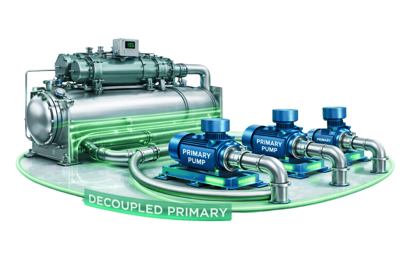
A decoupled plant has more working parts than a primary-only plant: two sets of pumps, a decoupler, flow and temperature instrumentation, and staging logic that ties them together. If any one of these is wrong, the whole plant suffers. The most common causes of poor performance in existing plants are:
- undersized decouplers
- badly placed sensors
- chiller staging that ignores decoupler flow
Compress India engineers every part of the plant together:
- 1. Plant assessment: we review loads, operating hours, chiller data and existing pump performance.
- 2. Hydraulic design: we calculate primary and secondary flows, pump heads, and decoupler and header sizes.
- 3. Equipment selection: we select primary pumps, secondary pumps, VFDs, valves and instrumentation.
- 4. Control sequence design: we define chiller staging, secondary pump sequencing and DP control.
- 5. Installation: we install pumps, headers, the decoupler, piping, electrical work and controls.
- 6. TAB and commissioning: we verify flows in both loops, check the decoupler and test staging.
- 7. Lifecycle support: we provide trend reviews, optimization and AMC.
What Is a Decoupled Constant Primary System?
A decoupled constant primary system is a chilled water plant arrangement with two pumping loops:
- Primary chilled water loop: a constant speed primary pump for each chiller keeps a steady flow through its evaporator.
- Secondary chilled water loop: secondary pumps move water from the plant to the building's AHUs and FCUs.
A decoupler joins the two loops and carries any difference between primary and secondary flow. It is also called a common pipe or chilled water bypass pipe.
When the secondary pumps run at variable speed with two-way valves at the coils, the plant becomes a constant primary variable secondary system, often shortened to CPVS. Constant primary flow with variable secondary flow combines constant flow through the chillers with variable flow chilled water distribution to the building. The arrangement is also called a decoupled primary secondary system, a primary secondary HVAC system or a primary secondary chilled water system with decoupler.
What Is Hydraulic Decoupling in Chilled Water Systems?
Hydraulic decoupling separates two pumped circuits so that the pumps in one do not affect flow or pressure in the other. In a chilled water plant, the decoupler is a short, low-resistance pipe between the primary supply and return. Almost no pressure difference exists across it, so the primary pumps effectively see only the chillers, and the secondary pumps see only the building.
This hydraulic separation between the chiller and distribution loop lets a hydraulically decoupled chilled water system hold chiller flow constant while building flow varies. The same principle, known more broadly as hydraulic separation in HVAC, appears in heating systems as low loss headers and closely spaced tees.
Why Decouple the Primary Loop from the Secondary Loop?
Decoupling solves several design problems at once:
- Chiller protection: each chiller gets constant flow through its evaporator, whatever the building is doing.
- Variable building flow: secondary pumps vary flow with load, saving pumping energy.
- Independent pump design: primary pumps handle only chiller-side losses and secondary pumps only distribution losses, so each is sized for its own job.
- Simple chiller staging: each chiller and its primary pump start and stop together without disturbing building flow.
- Multiple zones: different buildings or zones can have their own secondary pumps, served from one central plant.
- Expandability: new chillers or new secondary zones can be added with limited disruption.
How a Decoupled Constant Primary System Works
1. Constant Flow Primary Loop Through Chillers
Each running chiller has a constant speed primary pump delivering its design evaporator flow. Constant flow through the chiller keeps its capacity control stable and its evaporator well inside safe flow limits.
2. Decoupler / Common Pipe Connecting Both Loops
Chilled water leaves the chillers and enters the supply header, and the secondary pumps draw from this header. The decoupler links the supply and return sides of the primary loop and carries whatever flow the two loops don't share.
3. Secondary Pumps Serving the Building Load
Secondary pumps deliver chilled water to AHUs and FCUs across the building. With VFDs and two-way valves, they vary speed to hold a differential pressure setpoint at the index circuit, so flow follows the load.
4. Surplus Flow Returning Through the Decoupler
When the chillers circulate more water than the building needs, the surplus flows through the decoupler from supply to return and goes back to the chillers unused. A small surplus is normal and healthy. A large one means too many chillers are running.
5. Chiller Staging Based on Decoupler Flow & Temperature
The decoupler shows how well chiller capacity matches building demand. When surplus flow exceeds one chiller's flow, a chiller and its pump can be stopped. When flow reverses, the building is drawing more water than the chillers supply, so another chiller is started.
Main Components of a Decoupled Constant Primary System
| Component | Role in the System |
|---|---|
| Chillers | Produce chilled water at the design supply temperature |
| Primary chilled water pumps | Constant speed pumps holding design flow through each chiller |
| Decoupler (common pipe) | Hydraulically separates the primary and secondary loops |
| Secondary chilled water pumps | Serve the building, usually with VFDs |
| VFDs for secondary pumps | Vary secondary flow with load |
| Supply and return headers | Distribute flow to and from chillers and pumps |
| Two-way control valves or PICVs | Let secondary flow vary with load at each coil |
| Decoupler flow meter | Measures flow size and direction in the decoupler |
| Temperature sensors | Measure primary and secondary supply and return temperatures |
| Differential pressure sensor | Controls secondary pump speed from the index circuit |
| Isolation valves, strainers and check valves | Allow maintenance and protect pumps and chillers |
| Chiller plant manager / BMS | Coordinates chillers, pumps, staging and alarms |
The Decoupler – Design & Function
Role of the Decoupler / Common Pipe
The chilled water decoupler is the heart of the primary secondary common pipe arrangement. It lets primary and secondary flows differ without the pumps fighting each other. It carries every litre the chillers produce that the building doesn't use. It also carries every litre the building draws beyond what the chillers supply.
Decoupler Sizing (Pipe Diameter & Length)
Size the decoupler for at least the design flow of the largest chiller, because the surplus can approach that chiller's full flow at low load. Keep velocity low: the decoupler is commonly the same diameter as the primary header or the largest chiller connection. It should be short, straight and free of restrictions. Some designers also specify a minimum straight length to limit turbulence and unwanted mixing at low decoupler flow.
Decoupler Location in the Plant Room
The decoupler sits in the plant room, between the secondary supply and secondary return connections. Following the direction of primary flow, the secondary supply must leave the primary supply header before the decoupler, and the secondary return must join the primary return after it. If these connections are reversed, return water short-circuits straight back into the supply.
Low Pressure Drop Requirement
The decoupler only works if its pressure drop is negligible compared with either loop. Valves, strainers or undersized pipe in the decoupler create a pressure difference between the loops, and the primary and secondary pumps start to interact. We keep the decoupler free of anything that adds resistance, apart from a full-bore bidirectional flow meter where specified.
Should a Check Valve Be Installed in the Decoupler?
Generally, no. A check valve blocks reverse flow, but it also puts the primary and secondary pumps in series whenever the building needs more flow than the chillers supply. The secondary pumps then pull extra water through the running chillers, and the loops are no longer independent.
Some designers use a check valve deliberately to limit low delta-T effects, but only after checking chiller flow limits and pump interaction. In most plants, fixing the cause of reverse flow is the better solution.
Decoupler Flow Conditions
Surplus Flow (Supply to Return Direction)
When primary flow exceeds secondary flow, cold supply water flows through the decoupler to the return. The chillers see slightly cooler return water, but the building still receives water at the design supply temperature. A modest surplus is the normal operating state.
Deficit Flow (Return to Supply Direction)
When secondary flow exceeds primary flow, warm return water flows backwards through the decoupler into the secondary supply. This is decoupler reverse flow, and it means the chillers are not supplying enough water for the building.
Balanced / Zero Decoupler Flow
When primary and secondary flows match, decoupler flow is close to zero. That is efficient but leaves no margin: any increase in building flow causes reverse flow. Staging logic therefore aims for a small surplus rather than exactly zero.
Effect of Reverse Flow on Supply Water Temperature (Blending)
Reverse flow blends warm return water into the building supply. Take a plant with 100 m³/h of primary flow at 6.7 °C, 125 m³/h of secondary flow and return water at 11.7 °C. The 25 m³/h shortfall is made up from the return and mixes into the supply, so the building receives water at about 7.7 °C instead of 6.7 °C.
The consequences then feed each other:
- coils lose capacity and dehumidification suffers
- valves open further to compensate
- secondary flow rises
- reverse flow grows worse
This primary secondary flow imbalance is the classic downward spiral of a low delta-T chilled water system.
Types of Decoupling Arrangements
Common Pipe Decoupler
A straight, low-resistance pipe connects the primary supply and return in the plant room. It is the standard arrangement for chiller plants, and the simplest to design, instrument and maintain.
Hydraulic Separator / Low Loss Header
A hydraulic separator is a large-diameter vessel with four connections, two for each loop, and very low internal velocity. It separates the loops hydraulically and often includes air venting and dirt separation. Hydraulic separators are common in heating systems and compact chilled water plants.
Closely Spaced Tees
A secondary circuit is connected to a primary loop through two tees placed very close together, commonly no more than about four pipe diameters apart. The pressure drop between the tees is negligible, so the secondary circuit stays hydraulically independent. This arrangement is widely used for heating circuits and zone loops.
Decoupled Tertiary Loop Arrangement
In large campuses and district cooling networks, each building can have its own tertiary pumps. These connect to the secondary distribution through a local decoupler or bridge, often with a control valve that limits the flow drawn from the secondary loop to protect return temperature. Each building manages its own flow, and the central plant stays stable.
Comparison Table – Decoupler Types
| Parameter | Common Pipe | Hydraulic Separator / Low Loss Header | Closely Spaced Tees | Tertiary Decoupled Loop |
|---|---|---|---|---|
| Typical use | Chiller plants | Heating and compact plants | Heating and zone circuits | Campuses and district cooling |
| Separation quality | Good, if short and unrestricted | Very good, due to low internal velocity | Good, if tees are close together | Good at building level |
| Air and dirt separation | No | Often built in | No | No |
| Space needed | Small | Moderate | Very small | Extra pumps and piping |
| Flow measurement | Easy with a bidirectional meter | Possible on the connections | Limited | At each building |
| Relative cost | Low | Moderate | Low | Higher |
Primary Pump Arrangements in Decoupled Systems
Dedicated Constant Speed Primary Pumps
Each chiller has its own primary chilled water pump, which starts and stops with it. Controls are simple, each chiller gets its design flow, and unequal chillers are easy to accommodate. Standby can be provided per pump or through crossover piping.
Headered Constant Speed Primary Pumps
Primary pumps discharge into a common header serving all chillers, with a motorized isolation valve on each chiller. Any pump can serve any chiller, and one standby covers all duty pumps. Flow distribution between chillers needs careful design, especially when chiller sizes differ.
Comparison Table – Dedicated vs Headered Primary Pumps
| Parameter | Dedicated Primary Pumps | Headered Primary Pumps |
|---|---|---|
| Pump-to-chiller relationship | One pump per chiller | Any pump serves any chiller |
| Controls | Simple; the pump starts with its chiller | Needs isolation valves and sequencing |
| Unequal chiller sizes | Easy; pumps sized per chiller | Harder; the flow split must be managed |
| Standby provision | Per pump, or through crossover piping | One shared standby for all pumps |
| Flow through idle chillers | Stops with the pump | Stopped by isolation valves |
| Best suited for | Most decoupled plants | Identical chillers with a shared standby |
Secondary Pumping Options in Decoupled Systems
Constant Speed Secondary Pumps
Constant speed secondary pumps with three-way valves at the coils create a simple, constant flow secondary loop. They offer none of the energy savings of variable secondary flow. They also force enough chillers to run to match full secondary flow at all times.
Variable Speed (VFD) Secondary Pumps
A variable speed secondary pump on a VFD is the standard modern choice. It is controlled by chilled water differential pressure control at the index circuit, with a two-way control valve at each coil. Secondary flow follows the load and pumping energy falls sharply at part load. This variable secondary flow system is the heart of a CPVS chilled water system.
Zone / Building-Wise Secondary Pumps
Instead of one secondary pump set for the whole site, each zone or building can have its own secondary pumps drawing from the primary header. Each set is sized for its own zone's flow and head. Short, low-head zones are then not over-pressurized just to serve long, high-head ones.
Standby Secondary Pumps (N+1 Arrangement)
Secondary pumps are normally arranged as N+1, for example two duty and one standby. The standby is included in rotation and starts automatically if a duty pump faults.
Chiller Staging Using Decoupler Measurements
Decoupler Flow Meter–Based Staging
A bidirectional flow meter in the decoupler measures both the size and the direction of flow. A chiller and its pump are added when reverse flow persists for a set time. One is removed when the surplus exceeds one chiller's flow, plus a margin, for a set time.
Decoupler Temperature Sensor–Based Staging
Temperature sensors at the decoupler, or on the secondary supply just downstream of it, reveal flow direction. If the secondary supply temperature rises above the chiller leaving temperature, return water is blending in and another chiller is needed. The method is simple and robust, but slower and less precise than flow measurement.
Load (TR) Based Staging
The building load is calculated from secondary flow and delta-T, and the number of running chillers is matched to it using suitable thresholds. Load-based staging works well while delta-T is healthy. When delta-T is low, flow-based checks must be added, because the plant can run out of flow before it runs out of capacity.
Preventing Chiller Short Cycling
Short cycling is prevented by three measures:
- minimum run and off times
- time delays on staging decisions
- a deadband between stage-up and stage-down thresholds
Stage-up decisions also consider supply temperature, so a brief flow spike doesn't start an unnecessary chiller.
Benefits of Decoupled Constant Primary Systems
Constant and Protected Chiller Evaporator Flow
Constant evaporator flow keeps every chiller in its comfort zone. There is no risk of chiller flow falling below minimum as building load drops.
Independent Operation of Primary and Secondary Loops
Primary pumps serve the chillers and secondary pumps serve the building, and neither disturbs the other. Each loop can be designed, controlled and maintained separately.
Hydraulic Stability Across the System
Chillers starting and stopping don't upset building pressures. Building valves opening and closing don't change chiller flow.
Simple Chiller–Pump Staging
Each chiller and its primary pump start and stop as a pair. Decoupler flow gives a clear, measurable staging signal.
Flexibility to Serve Multiple Zones or Buildings
One central plant can feed separate secondary pump sets for zones or buildings with very different pressure requirements.
Easy Future Expansion
New chillers can be added to the primary loop and new zones to the secondary header, often without redesigning the existing systems.
Want to know how well your decoupled plant is really performing? Ask Compress India for a plant performance review.
Limitations & Design Challenges
Low Delta-T Syndrome
When building delta-T falls below design, secondary flow rises above what the running chillers supply. The plant has to start chillers for flow rather than capacity, and efficiency falls.
Reverse Flow & Supply Temperature Rise
Reverse decoupler flow blends return water into the supply. This raises the supply temperature and weakens dehumidification, which in turn drives even more secondary flow.
Constant Primary Pumping Energy
Primary pumps run at full speed whenever their chiller runs. Their energy falls only when chillers are staged off, not as building load falls.
Extra Chillers Running at Part Load
With low delta-T, the plant often runs one more chiller than the load needs, with every chiller lightly loaded, which raises kW/TR.
Higher Pump Count and Plant Room Space
Two sets of pumps, a decoupler and extra instrumentation take up more space, cost more and need more maintenance than a primary-only design.
Decoupled Constant Primary vs Primary Constant Flow (Primary-Only) Systems
| Parameter | Decoupled Constant Primary | Primary Constant Flow (Primary-Only) |
|---|---|---|
| Pump sets | Primary and secondary | One |
| Building flow | Variable, with VFD secondary pumps | Constant |
| Terminal valves | Two-way or PICVs | Three-way |
| Chiller flow | Constant | Constant |
| Idle chiller blending | Avoided; pumps stop with chillers | Possible in parallel plants |
| Pumping energy at part load | Lower | High |
| Capital cost | Higher | Lower |
| Best suited for | Medium to large, multi-chiller plants | Small and single-chiller plants |
Primary-only constant flow suits small, simple plants. Once a plant has several chillers or a large distribution network, decoupling usually pays for itself.
Decoupled Constant Primary vs Variable Primary Flow (VPF) Systems
Primary secondary vs variable primary flow is one of the most debated choices in chiller plant design. Constant primary variable secondary vs variable primary flow comes down to simplicity and chiller protection on one side, and the lowest energy use and pump count on the other.
| Parameter | Decoupled Constant Primary (CPVS) | Variable Primary Flow |
|---|---|---|
| Pump sets | Primary and secondary | One set of variable speed pumps |
| Chiller flow | Constant | Varies within chiller limits |
| Minimum flow protection | Inherent | Bypass valve with flow measurement |
| Pumping energy | Moderate | Lowest |
| Control complexity | Moderate | Higher |
| Chiller flow tolerance required | None | Chillers must handle flow variation |
| Plant room space | More | Less |
| Chiller staging | Simple, based on the decoupler | Needs careful flow and bypass control |
VPF saves more energy when it is well designed and well operated. CPVS remains the safer choice in three situations: older chillers that need constant flow, operators who value simplicity, and sites with several distinct zones.
Decoupled Constant Primary vs Variable Primary with Secondary Loop
In a variable primary with secondary loop arrangement, the primary pumps also get VFDs. They vary chiller flow within the chillers' limits and track secondary flow to keep a small, controlled surplus in the decoupler. Secondary pumps continue to serve the building. The plant keeps its decoupler and zone flexibility, while primary pumping energy falls and low delta-T problems ease.
| Parameter | Decoupled Constant Primary | Variable Primary with Secondary Loop |
|---|---|---|
| Primary pumps | Constant speed | Variable speed, tracking secondary flow |
| Chiller flow | Constant | Varies within chiller limits |
| Decoupler flow | Can swing between large surplus and reverse flow | Held at a small controlled surplus |
| Primary pumping energy | Constant for each running chiller | Reduced at part load |
| Low delta-T tolerance | Poor | Better; primary flow can rise within chiller limits |
| Controls | Moderate | More complex |
| Upgrade path | Base design | Add VFDs and controls to the primary pumps |
ECBC & ASHRAE 90.1 Considerations for Decoupled Systems
Decoupled plants fit comfortably within energy codes when the secondary loop is designed for variable flow. ECBC and ASHRAE 90.1 generally expect larger chilled water systems to:
- use two-way valves, so building flow varies with load
- reduce pump power at part load, typically through VFD secondary pumps
ASHRAE 90.1 adds further expectations:
- differential pressure measured near the most remote or most demanding coil
- DP setpoint reset from valve positions where DDC controls allow
- automatic reduction of plant flow when a chiller shuts down in a multi-chiller plant, which dedicated primary pumps or automatic isolation valves provide
In practice, this plays out as follows:
- CPVS plants: VFD secondary pumps with two-way valves align well with these provisions.
- Constant secondary loops: loops with three-way valves may not comply above code thresholds.
- Green building projects: IGBC, GRIHA and LEED projects benefit further from DP reset and higher delta-T.
Compress India works with your MEP consultant to align the design with the code edition that applies to your project.
Decoupled Constant Primary Systems for HVAC
For commercial HVAC, a decoupled primary secondary chilled water distribution system remains one of the most dependable ways to serve large buildings and campuses. Compress India designs and builds these plants for office towers, malls, hospitals, hotels and IT parks. Every plant gets properly sized decouplers, VFD secondary pumps, two-way control valves or PICVs, and staging logic built around decoupler flow.
For existing HVAC plants, we identify what is holding performance back, whether low delta-T, reverse flow, constant speed secondary pumps or poor staging, and fix it step by step.
Decoupled Constant Primary Systems for Industrial & Process Cooling
Industrial sites often serve very different loads from one chiller plant: production processes, cleanrooms, offices and utilities. A decoupled system lets each load group have its own secondary pumps and control strategy while the chillers run at steady, protected flow.
Process loops that need a higher supply temperature can be served through a tertiary decoupled loop with a mixing valve. Critical process loads get dedicated, redundant secondary pumps. Compress India designs these plants with the redundancy, instrumentation and process-PLC integration that production demands.
Applications of Decoupled Constant Primary Systems
Commercial Buildings & Office Complexes
Large office buildings with several chillers are the classic decoupled application. VFD secondary pumps follow occupancy through the day, while chillers stage on decoupler flow.
Shopping Malls
Malls often have separate secondary loops for common areas, anchor stores and food courts. Decoupling lets each loop run to its own schedule and pressure while sharing one chiller plant.
Hospitals
Hospitals value the chiller protection and stability of CPVS. Critical zones such as OTs and ICUs can have dedicated secondary pumps with N+1 redundancy, fed from a stable primary loop.
Data Centers
Data halls need uninterrupted chilled water. Decoupled plants give chillers stable flow during staging, and redundant secondary pumps and instrumentation keep IT cooling secure as the facility grows.
Pharmaceutical Facilities
Cleanroom AHUs, process cooling and utilities can each have their own secondary loop. Predictable chiller operation and documented control sequences support consistent, auditable performance.
Manufacturing Plants
Production lines, compressor cooling and office areas can be served from separate secondary loops. Process loads keep steady conditions while comfort loads vary with occupancy.
Hotels
Guest room towers, banquet halls and back-of-house areas have very different load patterns. Zone secondary pumps serve each efficiently from a single central plant.
Airports & Metro Systems
Terminals and station networks cover large areas with long pipe runs. Zone or building-wise secondary pumps avoid over-pressurizing short runs to satisfy the longest ones.
IT Parks & Campuses
Central plants serving several buildings can give each building its own secondary or tertiary pumps. New buildings join the network as the campus grows.
District Cooling Plants
District cooling uses primary, secondary and tertiary loops at scale. Tertiary decoupling at energy transfer stations helps protect network delta-T and keeps each customer's flow under control.
Decoupled Constant Primary Systems for Centrifugal, Screw & Multiple-Chiller Plants
Decoupled constant primary systems were developed largely for plants with multiple large chillers, and they remain a strong match for:
- Centrifugal chillers: large centrifugal machines have traditionally been designed around steady evaporator flow. A decoupled plant gives them constant flow while the building runs variable flow, and decoupler-based staging keeps them well loaded.
- Screw chillers: medium-sized screw chillers in multi-chiller plants benefit from dedicated primary pumps that start and stop with each machine, so flows don't change during staging.
- Multiple and unequal chillers: plants that mix chiller sizes or types are easy to handle with dedicated primary pumps sized for each chiller. A typical example is a large centrifugal paired with a smaller screw for low loads.
- Older chillers: where chillers cannot tolerate variable evaporator flow, CPVS is the natural choice over VPF.
We confirm each chiller's flow limits, evaporator pressure drop and staging requirements with the manufacturer's data before finalizing the primary pump design.
System Design & Sizing
Chilled Water Flow Calculation (GPM / m³/hr per TR)
Primary flow is set chiller by chiller. At a 10 °F (about 5.6 °C) delta-T, each TR needs about 2.4 GPM, or roughly 0.55 m³/h. A plant with three 300 TR chillers therefore needs about 720 GPM (164 m³/h) per chiller, or 2,160 GPM (about 491 m³/h) in total.
Secondary design flow comes from the building load and coil delta-T. Many designers set primary flow slightly above secondary design flow, so the decoupler stays in surplus at design conditions.
Primary Pump Head Calculation
Primary pumps overcome only the chiller-side losses:
- the evaporator
- primary piping and headers
- valves and strainers
- the decoupler, whose loss should be negligible
Building distribution losses are excluded, so primary head is usually modest and primary pump power stays low.
Secondary Pump Head Calculation
Secondary pumps overcome the distribution losses. The path starts at the supply-side decoupler connection, runs through the risers and branches to the index coil and its control valve, and ends at the return-side connection. The chillers are excluded, and the DP setpoint at the index circuit forms part of this head.
Chilled Water Delta-T Selection
Delta-T links everything in a decoupled plant. A higher design delta-T reduces primary and secondary flow, pipe sizes and pump power, provided the coils are selected to deliver it. Protecting delta-T in operation matters just as much as designing for it, because low delta-T drives reverse flow and extra chillers.
Decoupler and Header Sizing
The decoupler is sized for at least the largest chiller's design flow at low velocity. Headers are also sized for low velocities, so every chiller and pump connected to them sees nearly equal pressure and flow divides evenly.
Number of Pumps & Redundancy Selection
Primary pumps are usually one per chiller, with standby provision. Secondary pumps are typically N+1: two duty and one standby, or three duty and one standby for larger plants. Critical facilities may also add redundancy to instrumentation and controls.
Pump Selection Criteria
End-Suction vs Split-Case Pumps
End-suction pumps suit small to medium primary and secondary duties at low cost. Split-case pumps suit larger secondary duties with high flow, offering high efficiency and easy access to the rotating assembly.
Inline Pumps
Vertical inline pumps save floor space and suit primary duty in compact plant rooms, where they can be mounted directly in the chiller piping.
Pump Efficiency and Best Efficiency Point (BEP)
A constant speed primary pump runs at one duty point, so it is selected at or very near BEP. Variable speed secondary pumps are selected with the design point slightly to the right of BEP, so they stay efficient as speed falls at part load.
Motor & VFD Selection
IE3 or IE4 motors reduce losses on both loops. Secondary pump VFDs are sized on motor full-load current, rated for variable torque duty, and specified with harmonic mitigation and BMS communication.
Piping Layout & Plant Room Arrangement
Primary Loop Piping
The primary loop runs from the primary pumps through the chillers to the supply header, then from the return header back to the pumps. The layout keeps evaporator connections straightforward and each chiller easy to isolate.
Decoupler Piping Arrangement
The decoupler is a straight, unrestricted pipe between the supply and return headers. In the direction of primary flow, the secondary supply connects before it and the secondary return after it. A bidirectional flow meter is installed with the straight runs it needs.
Secondary Loop & Zone Piping
Secondary pumps draw from the supply header and discharge into risers and zone mains. Where zones have their own pumps, each set gets its own suction and discharge connections, check valves and isolation valves.
Valves, Strainers, Check Valves & Flexible Connections
Every pump gets isolation valves, a strainer or suction diffuser, a non-slam check valve on the discharge and flexible connections. Chillers get isolation valves, which are motorized in headered designs.
Insulation of Chilled Water Piping
All primary, secondary and decoupler piping, valves and fittings need insulation with a continuous vapour barrier. In Mumbai's humidity, any gap quickly leads to condensation, corrosion and lost cooling.
Instrumentation for Decoupled Systems
Decoupler Flow Meter
A bidirectional electromagnetic or ultrasonic flow meter measures both the size and direction of decoupler flow. It must read accurately at low flows, because the most important staging decisions happen near zero flow.
Supply & Return Temperature Sensors
Sensors at four points reveal blending, delta-T and load:
- chiller leaving water
- secondary supply, downstream of the decoupler
- secondary return
- primary return, after the decoupler
Immersion sensors in thermowells give the accuracy these calculations need.
Differential Pressure Sensors for the Secondary Loop
A DP transmitter at or near the index circuit controls secondary pump speed. Large or branched systems may use several sensors, with control based on whichever is furthest below its setpoint.
Sensor Location & Calibration
Temperature sensors must sit where the water is well mixed, and the flow meter needs its required straight runs. Every sensor is calibrated at commissioning and checked during maintenance, because small errors can trigger wrong staging decisions.
Controls, Automation & BMS Integration
Chiller–Primary Pump Interlocking
Each primary pump starts before its chiller and proves flow before the compressor is allowed to run. After the chiller stops, the pump runs on for a set time. A pump failure trips the chiller and starts the standby pump.
Chiller Staging Logic Based on Decoupler Flow
Staging logic combines decoupler flow, secondary supply temperature and calculated load. It adds a chiller on sustained reverse flow or a rise in supply temperature. It removes one when surplus flow exceeds a chiller's flow plus a margin. Time delays apply to every decision.
Secondary Pump Sequencing Logic
Secondary pumps run on DP control with matched speeds, stage on speed or flow thresholds, and rotate lead and lag by run hours. A failed pump is skipped and the standby starts automatically.
Decoupler Flow & Temperature Monitoring
Trends of decoupler flow and temperature show how often the plant runs in reverse flow, how large the surplus is, and how well chiller staging matches the load. They are the single most useful diagnostic in a decoupled plant.
Chiller Plant Manager & BMS Integration
The chiller plant manager coordinates chillers, primary pumps, secondary pumps, cooling towers and valves, and connects to the BMS over BACnet or Modbus. Operators get live plant graphics, trends, alarms and energy reports.
Energy Efficiency & Power Consumption
Pumping Energy Calculation
Pump power is calculated as:
Pump power (kW) = Flow (m³/h) × Head (m) ÷ (367 × pump-motor efficiency)
In the 3 × 300 TR example:
- Primary: each constant speed primary pump moves 164 m³/h at 15 m head with 72% efficiency, drawing about 9.3 kW whenever its chiller runs.
- Secondary: at design, 491 m³/h at 30 m head with 75% efficiency needs about 53.5 kW. This falls steeply at part load under VFD control.
Plant kW/TR Calculation
Plant kW/TR is calculated as:
Plant kW/TR = Total plant power (chillers, primary and secondary pumps, condenser pumps and cooling tower fans) ÷ Cooling delivered (TR)
The pumping share alone shows why secondary control matters. Take the example plant at 450 TR:
- VFD secondary pumps with two-way valves: two chillers and two primary pumps carry the load. Pumping power is about 18.6 kW primary plus roughly 16 kW secondary, around 35 kW in total, or 0.077 kW/TR.
- Constant speed secondary pumps with three-way valves: secondary flow stays at 491 m³/h, so all three primary pumps must run to avoid reverse flow. Pumping power stays near 81 kW, or 0.18 kW/TR, and three chillers run lightly loaded instead of two.
Secondary power at half flow is taken as about 30% of design, allowing for the DP control head.
Plant Optimization Strategies
- Reset the secondary DP setpoint based on valve positions
- Stage chillers on decoupler flow and temperature, not load alone
- Protect delta-T with two-way valves or PICVs, clean coils and correct setpoints
- Reset chilled water supply temperature where dehumidification allows
- Trim primary pumps to each chiller's exact design flow
- Optimize condenser water and cooling tower operation alongside the chilled water side
Installation of Decoupled Constant Primary Systems
Compress India installs decoupled plants in a planned sequence:
- 1. Plant room layout: we arrange chillers, primary pumps, secondary pumps, headers and the decoupler for access and correct hydraulic order.
- 2. Foundations and pump setting: we build inertia bases or plinths, then level and align each pump.
- 3. Primary loop and headers: we install piping, chiller connections, isolation valves and strainers.
- 4. Decoupler: we build a straight run with the correct connection order, and fit the flow meter with its required straight lengths.
- 5. Secondary pumps and distribution: we connect the pumps, risers and zone mains.
- 6. Electrical works: we install primary pump starters, secondary VFD panels, cabling and earthing.
- 7. Instrumentation and controls: we fit the flow meter, temperature sensors and DP sensors, and connect the chiller plant manager and BMS.
- 8. Flushing and insulation: we flush, fill and pressure test the system, then insulate it.
Testing, Balancing & Commissioning (TAB)
Decoupler Flow Verification
We confirm that the decoupler flow meter reads correctly in both directions, and that decoupler flow equals the difference between primary and secondary flows. We also check that the temperature sensors respond correctly to surplus and reverse flow.
Primary & Secondary Flow Balancing
Each chiller's primary flow is set to its design value and verified against evaporator pressure drop. Secondary flows are balanced to terminal design flows, and the secondary DP setpoint is established at the index circuit.
Chiller Staging Sequence Testing
We test every part of the staging sequence:
- stage-up on reverse flow and on supply temperature rise
- stage-down on surplus flow
- time delays and minimum run times
- pump failure responses
- restart after a power failure
Maintenance & AMC for Decoupled Chilled Water Systems
A decoupled plant depends on accurate measurement and healthy pumps on both loops. Compress India's AMC typically includes:
- Calibration checks on the decoupler flow meter and temperature sensors
- Trend reviews of decoupler flow, delta-T and chiller staging
- Primary and secondary pump inspections for vibration, bearings, seals and alignment
- VFD checks on the secondary pumps
- Strainer cleaning on both loops
- Chiller evaporator flow and pressure drop checks
- DP sensor calibration and setpoint reviews
- Water treatment monitoring and insulation inspections
AMC plans can be comprehensive or non-comprehensive.
Common Problems & Troubleshooting
Excess Surplus Flow in the Decoupler
A large, constant surplus usually means too many chillers are running, staging thresholds are wrong, or primary pumps are delivering more than design flow. Retuning the staging and trimming the primary pumps fixes it.
Reverse Decoupler Flow & Supply Temperature Rise
Reverse flow happens when secondary flow exceeds primary flow. The usual causes are low delta-T, too few chillers running, or secondary pumps overpumping because of high DP setpoints. The fixes are to raise delta-T, stage chillers correctly and reset the DP setpoint.
Low Delta-T
Low delta-T usually comes from one or more of:
- three-way valves still in the secondary loop
- oversized or leaking two-way valves
- fouled coils
- low supply air setpoints
- uncontrolled bypasses
PICVs, coil cleaning, valve audits and setpoint reviews raise delta-T.
Chiller Short Cycling
Short cycling comes from staging thresholds set too close together, missing time delays, or staging on a noisy flow signal. Deadbands, delays and signal filtering stop it.
Insufficient Flow at Remote Zones
Remote zones usually starve because of a low DP setpoint, a DP sensor in the wrong place, balancing problems or trapped air. Relocating sensors, raising or resetting the setpoint and rebalancing restore flow.
Pump Cavitation & Vibration
Low suction pressure, blocked strainers, air in the system, or secondary pumps running far out on their curves can all cause cavitation. Checking pressurization, cleaning strainers, venting and correcting pump operating points resolve most cases.
Retrofitting & Upgrading Decoupled Systems
Many older decoupled plants were built with constant speed secondary pumps and three-way valves. Upgrading them unlocks significant savings without replacing the chillers.
Adding VFDs to Secondary Pumps
VFDs on the secondary pumps, together with a DP sensor at the index circuit, let secondary flow follow the load. This is usually the highest-value upgrade in a decoupled plant.
Replacing Three-Way Valves with Two-Way Valves / PICVs
Converting the terminal valves makes the secondary loop truly variable flow. PICVs go further, adding automatic balancing and delta-T protection that directly reduce reverse flow.
Adding Decoupler Flow Meters & Controls
Many older plants stage chillers manually or on return temperature alone. Adding a bidirectional decoupler flow meter, temperature sensors and staging logic matches chiller operation to actual demand.
Converting to Variable Primary Flow
Where the chillers can handle variable evaporator flow, the plant can be converted to VPF. The conversion adds VFDs to the pumps, a bypass valve with flow measurement and new controls, and often removes one pump set. We confirm chiller flow limits and rate-of-change tolerances first.
Running a decoupled plant with constant speed secondary pumps? Ask Compress India for an upgrade assessment.
Decoupled Constant Primary System Cost in India
The cost of a decoupled constant primary system depends on plant capacity, the number of chillers, the secondary pumping arrangement, the extent of instrumentation and the controls scope. A two-chiller office plant is a very different investment from a multi-chiller campus plant with zone secondary pumps.
Compress India provides itemized proposals covering pumps, VFDs, piping, the decoupler, instrumentation, controls and commissioning. For larger plants, we also compare CPVS with variable primary options, so you can weigh capital cost against lifecycle energy.
Factors Affecting Project Cost
- Plant capacity, number of chillers and chiller types
- Dedicated or headered primary pumps
- Number and size of secondary pumps, and the zone arrangement
- VFDs, harmonic mitigation and panel arrangement
- Decoupler, headers and plant room piping
- Flow meters, temperature sensors and DP sensors
- Two-way valves or PICVs at the terminals
- Chiller plant manager and BMS integration
- Retrofit constraints, shutdown windows and phasing
- Testing, balancing, commissioning and AMC scope
Information Required for a Quotation
To prepare an accurate proposal, please share:
- Chiller details: number, capacity, type, evaporator flow and pressure drop
- Existing or proposed primary and secondary pump schedules
- Building load profile and operating hours
- Chilled water schematic showing primary, secondary and decoupler arrangements
- Terminal valve types, whether two-way, three-way or PICVs
- Existing controls, chiller plant manager and BMS details
- Plant room drawings or photographs
- For existing plants: current problems such as low delta-T, reverse flow or high energy use
- Energy bills and any planned expansion
Don't have everything ready? Our engineers can gather missing details during a site visit.
Decoupled Constant Primary System Contractor in Mumbai
Looking for a decoupled constant primary system contractor in Mumbai? Compress India designs new primary secondary plants and upgrades existing ones across the city. Many of Mumbai's large commercial complexes, hospitals and hotels run decoupled plants built with constant speed secondary pumps, three-way valves and manual chiller staging. Those plants now have large, measurable room for improvement.
We help in two ways. For new projects, we engineer decoupled plants with correct decoupler sizing, VFD secondary pumps and staging on decoupler flow. For existing plants, we deliver phased upgrades that cut energy use without interrupting cooling.
We work across Mumbai, including Cuffe Parade, Nariman Point, Tardeo, Worli, Lower Parel, BKC, Kalina, Saki Naka, Powai and Vikhroli.
Book a site visit with Compress India for your decoupled chilled water plant.
Chilled Water Pumping Solutions in Mumbai, Navi Mumbai, Thane & Maharashtra
Compress India supports chilled water pumping projects across Mumbai and the wider region:
- Navi Mumbai: Airoli, Ghansoli, Mahape, Belapur, Kharghar and Taloja
- Thane: Wagle Estate, Kolshet and Ghodbunder Road
- Pune: Hinjewadi, Kharadi and Magarpatta
- Rest of Maharashtra: Nashik, Nagpur and Chhatrapati Sambhajinagar
Our solutions include:
- New decoupled plants: primary and secondary pumping, decouplers and staging controls
- Secondary pump upgrades: VFDs, DP control and setpoint reset
- Terminal valve conversions: two-way valves and PICVs to raise delta-T
- Instrumentation upgrades: decoupler flow meters and temperature sensors
- VPF conversions: where chillers and operations support them
- AMC: pumps, VFDs, instrumentation and trend reviews
Decoupled Constant Primary System Solutions Across India
Beyond Maharashtra, Compress India takes up decoupled plant projects and upgrades across India, including Delhi NCR (Gurugram and Noida), Bengaluru, Hyderabad, Chennai, Kolkata and Ahmedabad. Large campuses, hospital groups and industrial sites in these cities often run multi-chiller plants where decoupler performance and delta-T largely decide the energy bill.
Every project follows the same design checks, instrumentation standards and commissioning procedures. For multi-site organizations, consistent trend reporting makes it easy to compare plant performance across locations.
Why Choose Compress India for Decoupled Constant Primary Systems?
Hydraulic Design Expertise
We size decouplers, headers and both pump loops from real flows and pressure drops, so the loops stay truly independent.
Complete Chiller Plant Integration
Chillers, primary pumps, secondary pumps, cooling towers and controls are designed as one plant, with staging that reflects actual demand.
Pump & Instrumentation Selection Support
We select pumps at the right point on their curves, and specify flow meters and sensors that read accurately where it matters most: near zero decoupler flow.
Control Sequence Engineering
We write and tune the chiller staging, secondary pump sequencing and DP control logic, and document it clearly for your operators.
Installation & Commissioning
Our execution team builds the plant in the correct hydraulic order, then verifies decoupler flow, loop balancing and staging before handover.
Retrofit & Energy Optimization
We diagnose reverse flow, low delta-T and staging problems in existing plants, then deliver phased upgrades with measurable results.
AMC & Lifecycle Support
Sensor calibration, trend reviews and pump care keep your decoupled plant stable and efficient year after year.
How to Select the Right Decoupled Pumping Arrangement
Every plant is different, but these guidelines are a good starting point:
- Multiple chillers, including older ones needing constant flow: CPVS with dedicated primary pumps
- Identical chillers with a need for shared standby: headered primary pumps with motorized chiller isolation
- Building loads that vary through the day: VFD secondary pumps with DP control and setpoint reset
- Several buildings or zones with different pressure needs: zone or building-wise secondary pumps
- Campuses and district cooling networks: tertiary decoupled loops at each building
- Compact heating or small mixed systems: a hydraulic separator or closely spaced tees
- Chillers that tolerate variable flow and an energy-first brief: variable primary flow, or variable primary with a secondary loop
- Existing plants with reverse flow and low delta-T: PICVs, a decoupler flow meter and staging upgrades first
Not sure which fits your site? A short plant review will show the right arrangement, and the savings it can deliver.
Get a Decoupled Constant Primary Solution from Compress India
Whether you need a new decoupled plant, a fix for reverse flow and low delta-T, or a staged upgrade to variable flow, Compress India delivers it with one accountable team.
Connect with Our HVAC Execution Team
Call our team or send an enquiry through this page with your chiller and pump details. Our engineers will review your plant and recommend a site visit where needed. You will then receive a clear proposal covering design, equipment, controls and expected savings.
Related Systems Types & Components
Explore our comprehensive range of hydronic system configurations and components designed for efficient water distribution.
Primary Constant Flow Systems
Learn More
Constant Flow with Three-Way Valve Control
Learn More
Boiler-Based Constant Flow Heating Systems
Learn More
Process Cooling Constant Flow Loops
Learn MoreFrequently Asked Questions
Q1. What is a decoupled constant primary system?
It is a chilled water plant with two pumping loops. Constant speed primary pumps keep steady flow through the chillers, and secondary pumps serve the building. A decoupler pipe joins the loops and keeps them hydraulically independent.
Q2. How does a decoupled constant primary chilled water system work?
Primary pumps circulate constant flow through each running chiller. Secondary pumps, usually on VFDs with two-way valves, deliver flow that follows the building load. The difference between the two flows passes through the decoupler, and chillers are staged based on that flow.
Q3. What is hydraulic decoupling?
Hydraulic decoupling separates two pumped circuits with a low-resistance connection, so the pumps in one circuit do not affect flow or pressure in the other.
Q4. What is a decoupler or common pipe?
A decoupler, also called a common pipe, is a short, low-resistance pipe between the primary supply and return. It carries the difference between primary and secondary flows.
Q5. How is a decoupler line sized?
It is sized for at least the design flow of the largest chiller at low velocity, and is commonly the same diameter as the primary header. It is kept short, straight and free of valves or other restrictions.
Q6. Where should the decoupler be located?
In the plant room, between the secondary supply and return connections. In the direction of primary flow, the secondary supply must be taken off before the decoupler and the secondary return must join after it.
Q7. Should a check valve be installed in the decoupler line?
Generally, no. A check valve puts the primary and secondary pumps in series during high demand and removes the hydraulic independence of the loops. It should only be used as a deliberate design choice, after checking chiller flow limits and pump interaction.
Q8. What happens when flow reverses in the decoupler?
Warm return water blends into the building supply and raises its temperature. For example, supply water can rise from 6.7 °C to about 7.7 °C. Coils lose capacity, valves open further and secondary flow rises, which makes the reverse flow worse.
Q9. What is the difference between surplus and deficit flow in the decoupler?
Surplus flow runs from supply to return when the chillers circulate more water than the building needs. Deficit, or reverse, flow runs from return to supply when the building needs more water than the chillers circulate.
Q10. What is a hydraulic separator or low loss header?
It is a large-diameter vessel with primary and secondary connections and very low internal velocity. It separates the loops hydraulically and often includes air venting and dirt separation.
Q11. How are chillers staged using decoupler flow?
A chiller and its pump are added when reverse flow persists for a set time. One is removed when surplus flow exceeds a chiller's flow plus a margin for a set time. Time delays and deadbands prevent short cycling.
Q12. Can secondary pumps be constant speed in a decoupled system?
Yes, when combined with three-way valves at the coils. However, this gives no pumping savings and forces enough chillers to run to match full secondary flow. VFD secondary pumps with two-way valves or PICVs are strongly recommended.
Q13. How much energy can VFD secondary pumps save in a decoupled system?
Secondary pumping energy often falls by 30–50% or more where loads vary. The plant can also run fewer chillers and primary pumps at part load. In our 900 TR example at half load, total pumping power fell from about 81 kW to about 35 kW.
Q14. What is low delta-T syndrome in decoupled systems?
It occurs when the building returns water cooler than design, so secondary flow exceeds what the running chillers supply. The plant then runs extra chillers for flow rather than capacity, often with reverse decoupler flow.
Q15. What is the difference between a decoupled constant primary system and variable primary flow?
A decoupled system uses constant speed primary pumps and separate secondary pumps, with constant flow through the chillers. Variable primary flow uses one set of variable speed pumps that vary flow through the chillers themselves. VPF uses the least energy; CPVS offers simpler staging and stronger chiller protection.
Q16. Is a decoupled constant primary system suitable for data centers and hospitals?
Yes. Stable chiller flow, independent loops and N+1 secondary pumps suit critical facilities well. Adding redundant instrumentation and careful staging logic further protects cooling continuity.
Q17. Can an existing decoupled system be converted to variable primary flow?
Yes, where the chillers can handle variable evaporator flow. The conversion adds pump VFDs, a bypass valve with flow measurement and new controls, and often removes one pump set. Chiller flow limits must be confirmed first.
Q18. What maintenance does a decoupled constant primary system need?
Typical maintenance covers:
- flow meter and sensor calibration
- trend reviews of decoupler flow and delta-T
- pump and VFD checks on both loops
- strainer cleaning
- chiller flow checks
- water treatment monitoring
- insulation inspections
Q19. What information is needed for a decoupled constant primary system quotation?
We need:
- chiller details and pump schedules
- the load profile and operating hours
- the chilled water schematic and terminal valve types
- controls and BMS details
- plant room drawings or photographs
- for existing plants, current problems and energy bills
Q20. Does Compress India design and install decoupled constant primary systems?
Yes. Compress India designs, installs and commissions decoupled constant primary systems across Mumbai, Maharashtra and India. We also upgrade existing plants with VFD secondary pumps, PICVs, decoupler instrumentation and variable primary conversions.